Configuring the gp488b interface dma channel – Measurement Computing Personal488 rev.1.0 User Manual
Page 35
Personal488 for Windows 95/98/Me/NT/2000/XP
889496
Hardware Configuration Reference 4-9
The GP488B interface board may be set to interrupt the PC on the occurrence of certain
hardware conditions. The level of the interrupt generated is set by J4. The GP488B adheres
to the “AT-style” interrupt sharing conventions. When an interrupt occurs, the interrupting
device must be reset by writing to I/O address 02FX, where X is the interrupt level (from 0 to
7). This interrupt response level is set by switches 1, 2, and 3 of SW1 which must be set to
correspond to the J4 interrupt level setting.
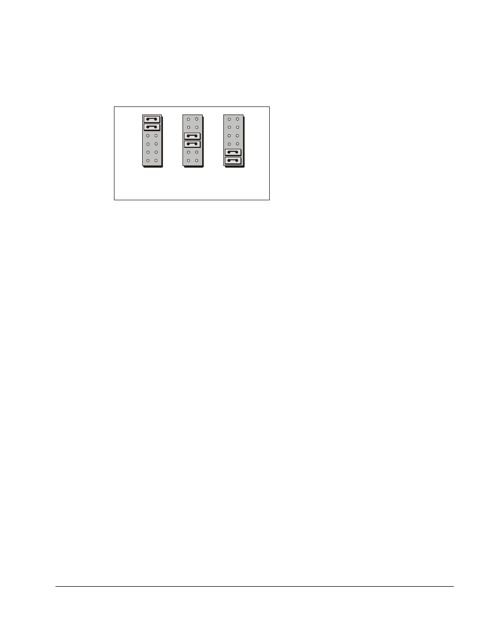
Configuring the GP488B Interface DMA Channel
J3
Channel 1
GP488B DMA Channel Selections
Channel 2
Channel 3
The factory default DMA channel is 1. If this creates a conflict, reset jumper J3 according to
the figure. If reset, record the new DMA channel being used.
Direct Memory Access (DMA) is a high-speed method of transferring data from or to a
peripheral, such as a digitizing oscilloscope, to or from the PC’s memory. The PC has four
DMA channels, but Channel 0 (Disabled) is used for memory refresh and is not available for
peripheral data transfer. Channel 2 is usually used by the floppy disk controller, and is also
unavailable. Channel 3 is often used by the hard disk controller in PCs, XTs, and the PS/2 with
the ISA bus, but is usually not used in ATs. So, depending on your hardware, DMA Channels 1
and possibly Channel 3 are available. Under some rare conditions, it is possible for high-speed
transfers on DMA Channel 1 to demand so much of the available bus bandwidth that
simultaneous access of a floppy controller will be starved for data due to the relative priorities
of the two channels.