At488 configurations, Configuring the at488 interface i/o base address, Selected i/o base address – Measurement Computing Personal488 rev.1.0 User Manual
Page 29: Register, At488 configurations …… 4-3
Personal488 for Windows 95/98/Me/NT/2000/XP
889496
Hardware Configuration Reference 4-3
AT488 Configurations
The I/O base address, IRQ, and DMA settings are switch/jumper selectable via the following
locations on the AT488 interface board: One 2-microswitch DIP switch labeled S1, one
4-microswitch DIP switch labeled S2, two 14-pin headers labeled DACK and DRQ, and one
22-pin header labeled IRQ. The DIP switch settings, and the arrangement of the jumpers on
the headers set the hardware configuration.
For the next steps, make sure that the I/O address, IRQ, and DMA set on the interface board
are different from any existing ports in your system. A conflict results when two I/O
addresses, IRQs, or DMAs are the same. (As the exception, additional AT488 interfaces may
share the same IRQ and DMA values.) If there is a conflict, reconfigure the switch/jumper
settings. Refer to the following figures as needed.
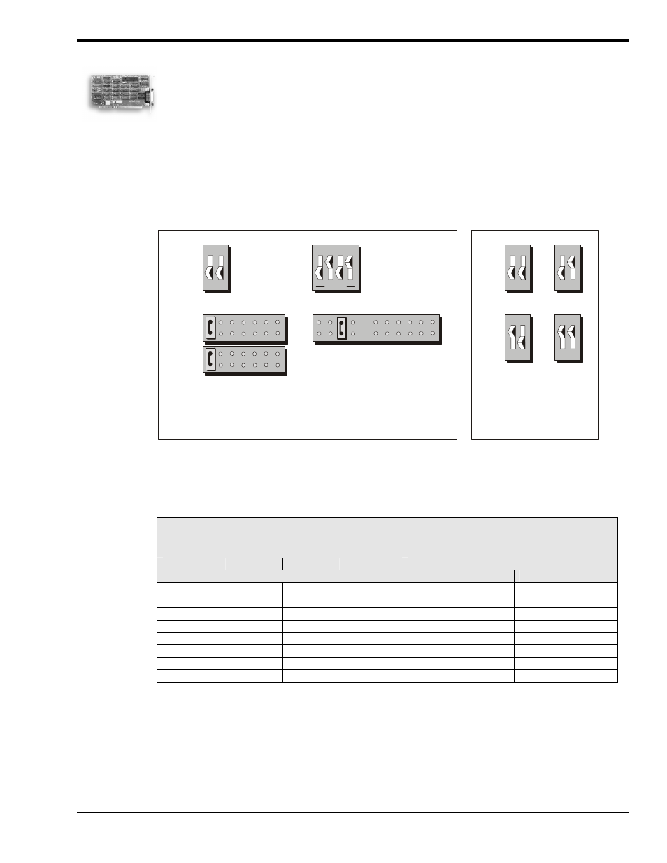
Configuring the AT488 Interface I/O Base Address
Interrupt Level 5
DMA 16-Bit Channel 5
Base Address
02E1
Interrupt
Level 5
AT488 Default Settings
S1
DACK
DRQ
IRQ
S2
AT488 I/O Base
Address Selections
S1
42E1
62E1
22E1
02E1
5 6 7 0 1 2 3
3
4
5
6
7
9
10
11
12
14
15
OPEN
OPEN
OPEN
OPEN
OPEN
1 2
1 2
1 2
1 2
1 2
1 2 3 4
OPEN
The factory default I/O base address is 02E1. If this creates a conflict, reset switch S1
according to the figure and following table. The register addresses will be automatically
relocated at fixed offsets from the base address. If reset, record the new Input/Output (I/O)
address being used.
Selected I/O Base
Address
02E1
22E1
42E1
62E1
Register
Automatic Offset Addresses
Read Register
Write Register
02E1 22E1 42E1 62E1
Data In
Data Out
06E1 26E1 46E1 66E1
Interrupt Status 1
Interrupt Mask 1
0AE1 2AE1 4AE1 6AE1
Interrupt Status 2
Interrupt Mask 2
0EE1 2EE1 4EE1 6EE1
Serial Poll Status
Serial Poll Mode
12E1 32E1 52E1 72E1
Address Status
Address Mode
16E1 36E1 56E1 76E1
CMD Pass Through Auxiliary Mode
1AE1 3AE1 5AE1 7AE1
Address 0
Address 0/1
1EE1 3EE1 5EE1 7EE1
Address 1
End of String
The I/O base address sets the addresses used by the computer to communicate with the IEEE
488 interface hardware on the board. The address is normally specified in hexadecimal and
can be 02E1, 22E1, 42E1, or 62E1. The registers of the IOT7210 IEEE 488 controller chip
and other auxiliary registers are then located at fixed offsets from the base address.
Most versions of Driver488 are capable of managing as many as four IEEE 488 interfaces. To
do so, the interface configurations must be arranged to avoid conflict amongst themselves.
No two boards may have the same I/O address; but they may, and usually should, have the
same DMA channel and interrupt level.