Configuring the at488 interface interrupt (irq) – Measurement Computing Personal488 rev.1.0 User Manual
Page 30
4-4 Hardware Configuration Reference
889496
Personal488 for Windows 95/98/Me/NT/2000/XP
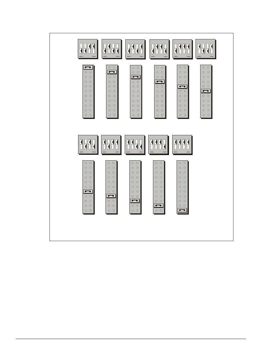
Configuring the AT488 Interface Interrupt (IRQ)
S2
S2
Interrupt
Level 10
Interrupt
Level 11
Interrupt
Level 12
Interrupt
Level 14
Interrupt
Level 15
IRQ
IRQ
3
4
5
6
7
9
10
11
12
14
15
3
4
5
6
7
9
10
11
12
14
15
Interrupt
Level 6
Interrupt
Level 9
AT488 Interrupt Selections
1 2 3 4
1 2 3 4
1 2 3 4
1 2 3 4
1 2 3 4
1 2 3 4
1 2 3 4
OPEN
OPEN
OPEN
OPEN
OPEN
OPEN
OPEN
Interrupt
Level 7
1 2 3 4
OPEN
Interrupt
Level 3
Interrupt
Level 4
1 2 3 4
1 2 3 4
OPEN
OPEN
Interrupt
Level 5
1 2 3 4
OPEN
The factory default Interrupt (IRQ) is 5. If this creates a conflict, reset switch S2 and
jumper IRQ according to the figure. The switch and jumper settings must both indicate
the same interrupt level for correct operation with interrupts. If reset, record the new
Interrupt (IRQ) being used.
The AT488 interface board may be set to interrupt the PC on the occurrence of certain
hardware conditions. The main board interrupt may be set to IRQ level 3 through 7, 9
through 12, 14, or 15. Interrupts 10 through 15 are only available in a 16-bit slot on an AT-
class machine. Interrupt 9 becomes synonymous with Interrupt 2 when used in a PC/XT bus.
The selected interrupt may be shared among several AT488s in the same PC/AT chassis. The
AT488 adheres to the “AT-style” interrupt sharing conventions. When the AT488 requires
service, the IRQ jumper determines which PC interrupt level is triggered. When an interrupt
occurs, the interrupting device must be reset by writing to an I/O address which is different
for each interrupt level. The switch settings determine the I/O address to which the board’s
interrupt rearm circuitry responds.