Gp488b/mm pc104 configurations, Selected i/o base address, Register – Measurement Computing Personal488 rev.1.0 User Manual
Page 37: Gp488b/mm configurations …… 4-11
Personal488 for Windows 95/98/Me/NT/2000/XP
889496
Hardware Configuration Reference 4-11
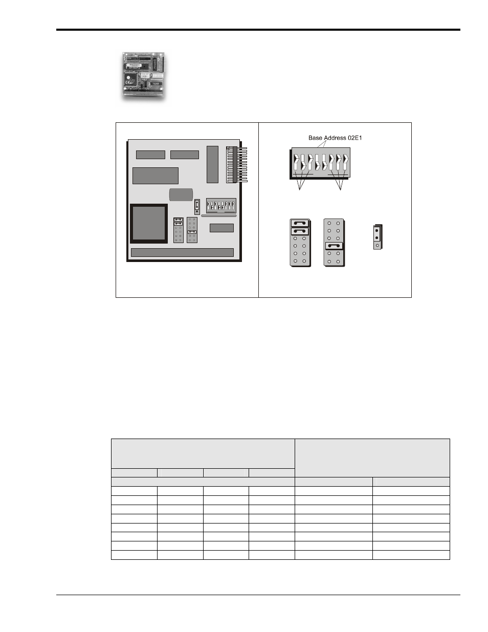
GP488B/MM PC104 Configurations
DMA
Channel 1
On-board
8 MHz Clock
SW1
JP1
JP2
JP3
P1
Interrupt
Level 5
JP2
JP3
JP1
GP488B/MM PC104 Interface Board
GP488B/MM PC104 Default Settings
No Wait
States
SW1
6 7 8
5
2 3
OPEN
1
4
6 7 8
5
2 3
O PEN
1
4
Interrupt
Level 5
The I/O base address, IRQ, and DMA settings are switch/jumper selectable via the
following locations on the GP488B/MM interface board: One 8-microswitch DIP switch
labeled SW1, two 12-pin headers labeled JP2 and JP3, and one 3-pin header labeled JP1.
The DIP switch settings and the arrangement of the jumpers [on the headers] set the
hardware configuration.
For the next steps, make sure that the I/O address, IRQ, and DMA, set on the interface
board are different from any existing ports in your system. A conflict results when two I/O
addresses, IRQs, or DMAs are the same. (As the exception, additional GP488B/MM
interfaces may share the same IRQ and DMA values). If there is a conflict, reconfigure the
switch/jumper settings. Refer to the following figures as needed.
Selected I/O Base
Address
02E1
22E1
42E1
62E1
Register
Automatic Offset Addresses
Read Register
Write Register
02E1 22E1 42E1 62E1
Data In
Data Out
06E1 26E1 46E1 66E1
Interrupt Status 1
Interrupt Mask 1
0AE1 2AE1 4AE1 6AE1
Interrupt Status 2
Interrupt Mask 2
0EE1 2EE1 4EE1 6EE1
Serial Poll Status
Serial Poll Mode
12E1 32E1 52E1 72E1
Address Status
Address Mode
16E1 36E1 56E1 76E1
CMD Pass Through Auxiliary Mode
1AE1 3AE1 5AE1 7AE1
Address 0
Address 0/1
1EE1 3EE1 5EE1 7EE1
Address 1
End of String