3 control lines – Measurement Computing Digital488 User Manual
Page 22
Section 2
Getting Started
2.6
45
SERVICE INPUT (Input).
46
EXTERNAL DATA READY [EDR] (Input).
47,48
Not used.
49
+5 Volts (Do not exceed 50 mA load).
50
I/O COMMON (Gnd).
2.3.3 Control Lines
Five control lines enable handshaking of digital I/O data transfer to the
Digital488. They are automatically activated with the corresponding I/O
activity and can also be independently activated with the Handshake (Hn)
command.
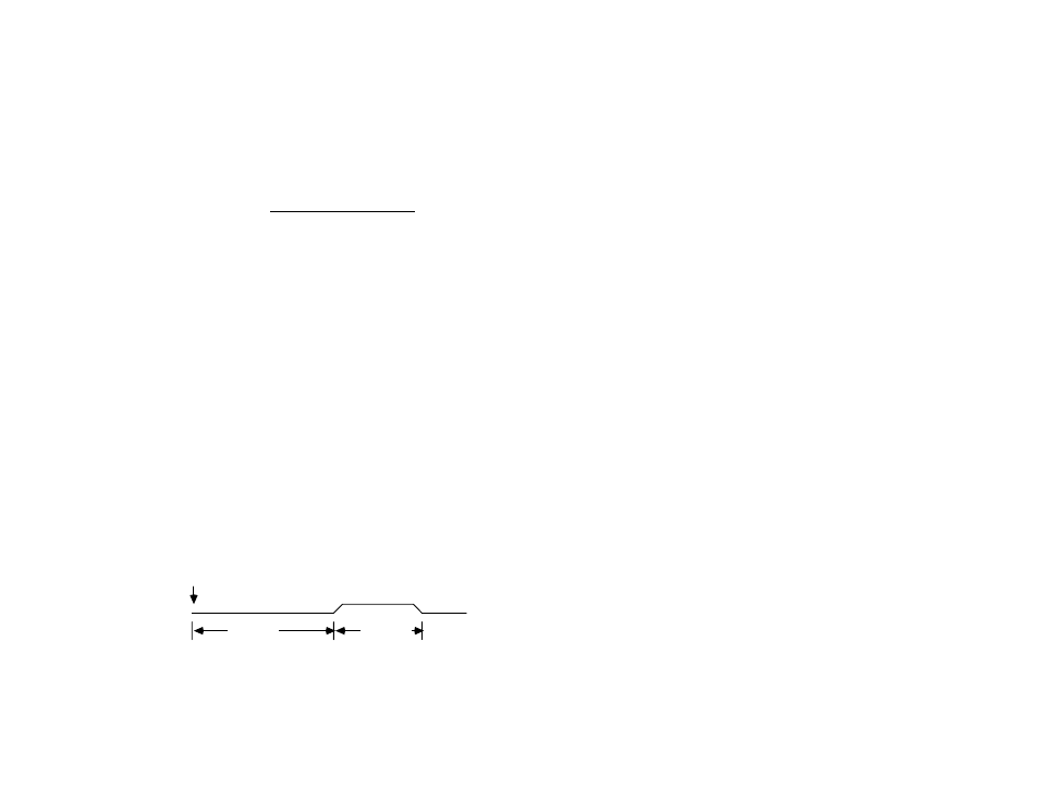
2.3.3.1 Clear (Pin 41)
The Clear output is pulse for approximately 50
microseconds after a Device Clear (DCL), Selected Device Clear
(SDC), or Interface Clear (IFC) command has been sent on the bus.
The Clear line is normally active high. The Invert command (I8)
will program it active low. The Handshake command (H0) can
pulse the Clear line, independent of any I/O operations.
Timing Diagram for Clear Output
Clear
65 µS typ
50 µS typ
DCL, SDC or IFC