1 ieee 488 address selection, 2 ieee 488 bus output terminator selection – Measurement Computing Digital488 User Manual
Page 18
Section 2
Getting Started
2.2
To modify any of these defaults, follow this simple procedure. Disconnect the
power supply from the AC line and from the interface. Disconnect any IEEE or
digital I/O cables prior to disassembly.
WARNING
Never open the Digital488 case while it is
connected to the AC line. Failure to observe the
warning may result in equipment failure, personal
injury or death.
Remove the four screws located in each corner of the rear panel. Hold the case
firmly and pull the rear panel outward, noting the slot location of the main circuit
board. Modify those parameters which are appropriate for your installation and
reassemble the unit. Slide the main circuit board into the previously noted slot and
finish reassembly by tightening the four screws into the rear panel.
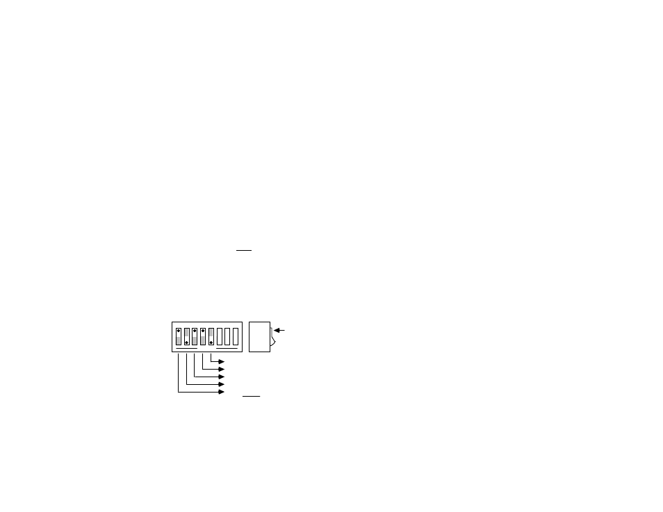
2.2.1 IEEE 488 Address Selection
The IEEE 488 bus address is set by SW1-1 through SW1-5. The
address can be set from 0 through 30 and is read only at power on. The
address is selected by simple binary weighting with SW1-1 being the least
significant bit and SW1-5 the most significant bit. The factory default is
address 18. If address 31 is selected, it defaults to address 30 because the
IEEE 488 standard has reserved address 31.
SW1 View for IEEE Bus Address Selection
OPEN
1 2 3 4 5 6 7 8
1
0
DOT
Switch
Side
View
1 x 16
0 x 8
0 x 4
1 x 2
0 x 1
= 0
= 0
= 2
= 0
+
IEEE Address = 18
= 16