Getting started, 1 inspection, 2 configuration – Measurement Computing Digital488 User Manual
Page 17
Section 2
Getting Started
2.1
Getting Started
2.1 Inspection
The Digital488 was carefully inspected, both mechanically and electrically,
prior to shipment. When you receive the interface, carefully unpack all items from
the shipping carton and check for any obvious signs of physical damage which may
have occurred during shipment. Report any such damage found to the shipping agent
immediately. Remember to retain all shipping materials in the event that shipment
back to the factory becomes necessary.
Every Digital488 is shipped with the following....
•
Digital488
IEEE Digital I/O Converter or
•
Digital488OEM
Board Level IEEE Digital I/O Converter
•
CN-8-50†
Digital I/O Port Mating Connector
•
110-0920
Instruction Manual
•
Power Supply†
TR-2; 115V or
•
TR-2E; 220V
†
Supplied with Digital488 Only and not the Digital488OEM
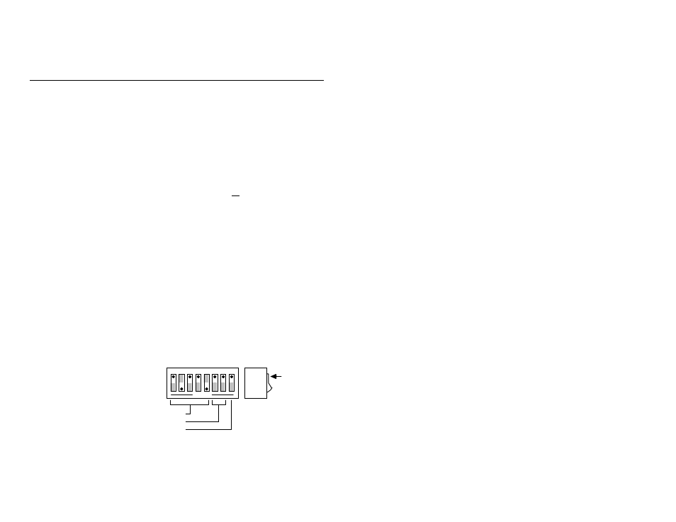
2.2 Configuration
The Digital488 has one internal 8 position switch which determines the unit's
IEEE address and its default IEEE bus output terminator. The switch is only read
when the unit is powered on, and should only be set prior to applying power. The
following figure illustrates the factory default setting for SW1.
SW1 Factory Default Settings
OPEN
1 2 3 4 5 6 7 8
1
0
DOT
Switch
Side
View
IEEE Address = 18
Terminator = CR-LF
EOI Enabled