Register definitions, Interrupt enable register – Measurement Computing COM232/8AT User Manual
Page 8
8 COM232/8AT User’s Guide
March 1998
1000-0901, rev 1.1
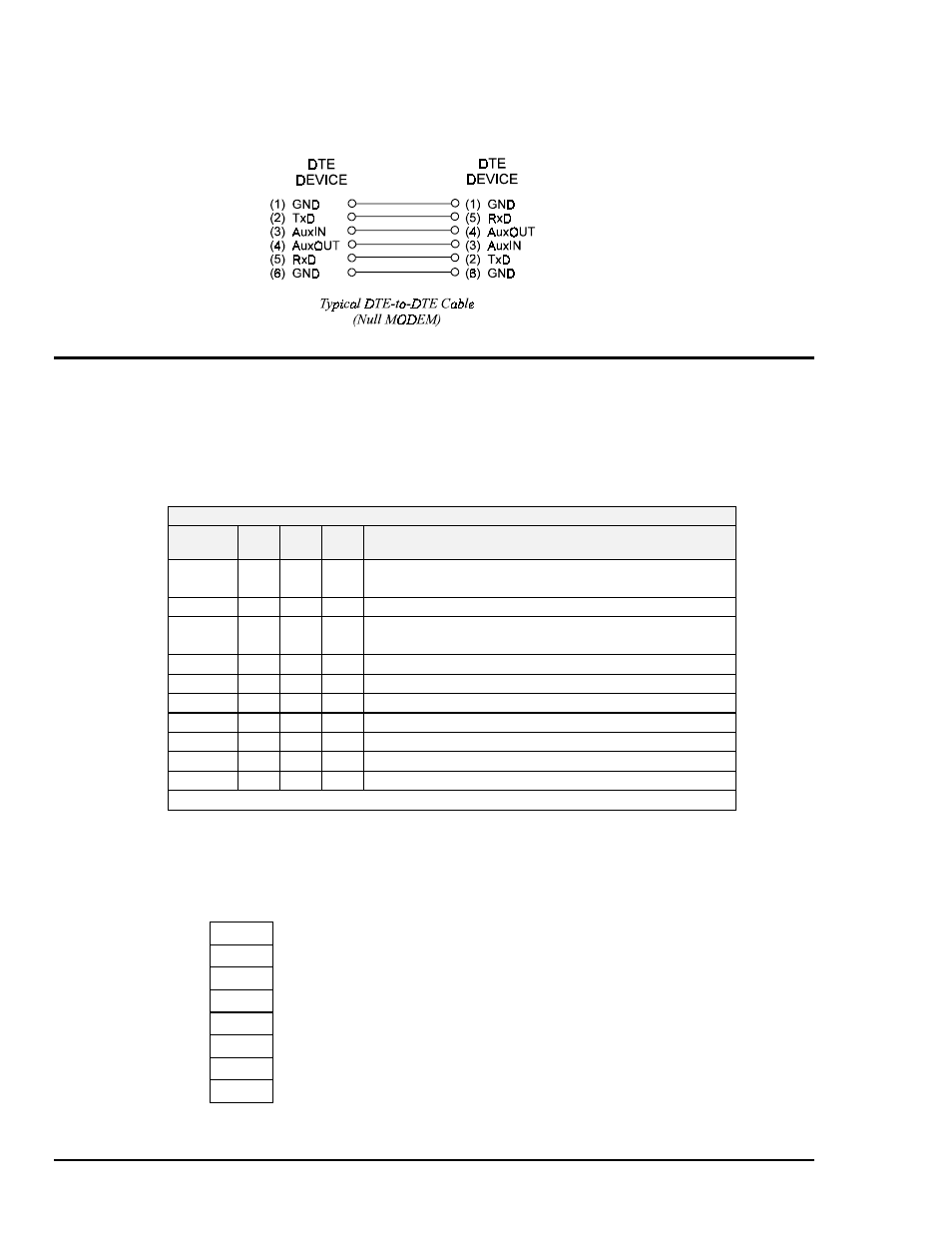
If you need to connect two DTEs together, you must make use of a customized cable known as a NULL MODEM or
MODEM Eliminator. A typical DTE-to-DTE cable is as follows:
Register Definitions
This section provides a brief summary of the 16550 ACE internal registers. The registers are addressed
as indicated in the following table.
Note:
The 16550 Asynchronous Communications Element (ACE) enters character mode on reset.
When the 16550 ACE is in character mode it appears as a 16450 ACE to the software.
16550 ACE Internal Register Map
DLAB
(see note)
A2
A1
A0
Description
0
0
0
0
Receive Buffer (read only)
Transmitter Holding Register (write only)
0
0
0
1
Interrupt Enable
x
0
1
0
Interrupt Identification (read only)
FIFO Control (write only)
x
0
1
1
Line Control
x
1
0
0
MODEM Control
x
1
0
1
Line Status
x
1
1
0
MODEM Status
x
1
1
1
Scratch
1
0
0
0
Divisor Latch (LSB)
1
0
0
1
Divisor Latch (MSB)
Note: DLAB is accessed through the Line Control Register.
Interrupt Enable Register
The bit definitions for the Interrupt Enable Register are as follows:
Interrupt Enable Register Definitions
D7
0
D6
0
D5
0
D4
0
D3
EDSSI
MODEM Status
D2
ELSI
Receiver Line Status
D1
ETBEI
Transmitter Holding Register Empty
D0
ERBFI
Received Data Available