Line control register – Measurement Computing COM232/8AT User Manual
Page 11
1000-0901, rev 1.1
March 1998
COM232/8AT User’s Guide
11
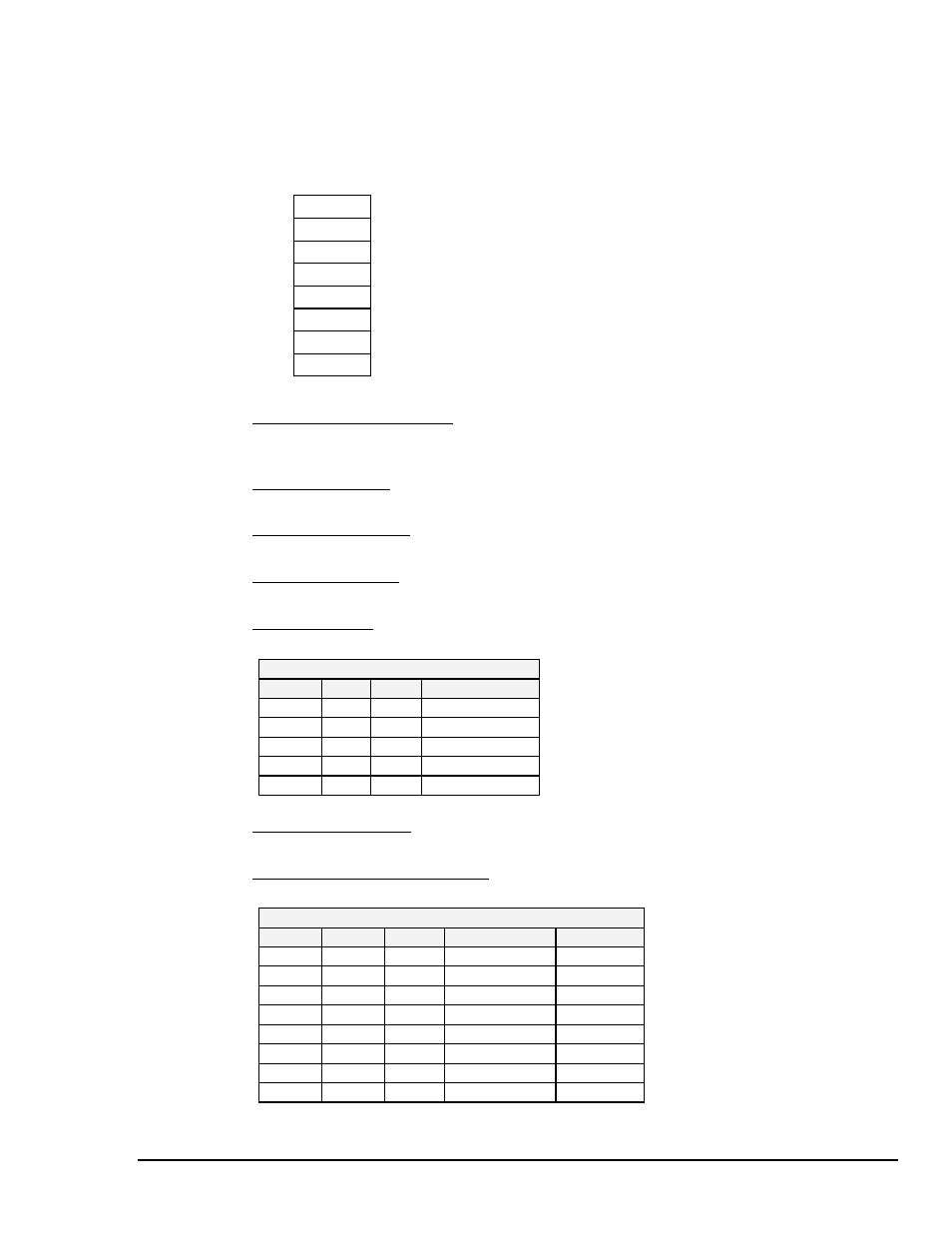
Line Control Register
The bit definitions for the Line Control Register are as follows:
Line Control Register Definitions
D7
DLAB
Divisor Latch Access Bit
D6
BKCN
Break Control
D5
STKP
Stick Parity
D4
EPS
Even Parity Select
D3
PEN
Parity Enable
D2
STB
Number of Stop Bits
D1
WLS1
Word Length Select 1
D0
WLS0
Word Length Select 0
DLAB Divisor Latch Access Bit
− DLAB must be set to logic 1 to access the baud rate divisor latches.
DLAB must be set to logic 0 to access the receiver buffer, transmitting holding register, and interrupt
enable register.
BKCN Break Control
− When set (logic 1), the serial output (SOUT) is forced to the spacing state
(logic 0).
STKP Stick Parity Select
− Forces parity to logic 1 or logic 0 if parity is enabled. Also see EPS, PEN,
and the following Parity Selections table.
EPS Even Parity Select
− Selects even or odd parity if parity is enabled. Also see STKP, PEN, and the
following Parity Selections table.
PEN Parity Enable
− Enables Parity on transmission and verification upon reception. Also see EPS,
STKP, and the following Parity Selections table.
Parity Selections
STKP
EPS
PEN
Parity
x
x
0
None
0
0
1
Odd
0
1
1
Even
1
0
1
Logic 1
1
1
1
Logic 2
STB Number of Stop Bits
− Sets the number of stop bits transmitted. Also see the following WLS1 &
WLS0 text and related Word Length table.
WLS1 & WLS0 Word Length Selects
− Determines the number of bits per transmitted word. Also
refer to STB and the following table.
Word Length & Stop Bit Selections
STB
WLS1
WLS0
Word Length
Stop Bits
0
0
0
5 bits
1
0
0
1
6 bits
1
0
1
0
7 bits
1
0
1
1
8 bits
1
1
0
0
5 bits
1-1/2
1
0
1
6 bits
2
1
1
0
7 bits
2
1
1
1
8 bits
2