Fifo interrupt mode operation, Divisor latch settings for common baud rates – Measurement Computing COM232/8AT User Manual
Page 15
1000-0901, rev 1.1
March 1998
COM232/8AT User’s Guide
15
FIFO Interrupt Mode Operation
When the receiver FIFO and receiver interrupts are enabled, interrupts will occur as follows:
1. The Received Data Available Interrupt (ERBFI) will be issued to the CPU when the FIFO reaches
the programmed trigger level. This interrupt will be cleared as soon as the FIFO falls below its
programmed trigger level.
2. The Interrupt Identification Register’s (IIR) receive data available indicator is set and cleared
along with the Received Data Available Interrupt (see 1 above).
3. The Data Ready (DR) indicator is set as soon as a character is transferred into the receiver FIFO.
The DR indicator is cleared when the FIFO is empty.
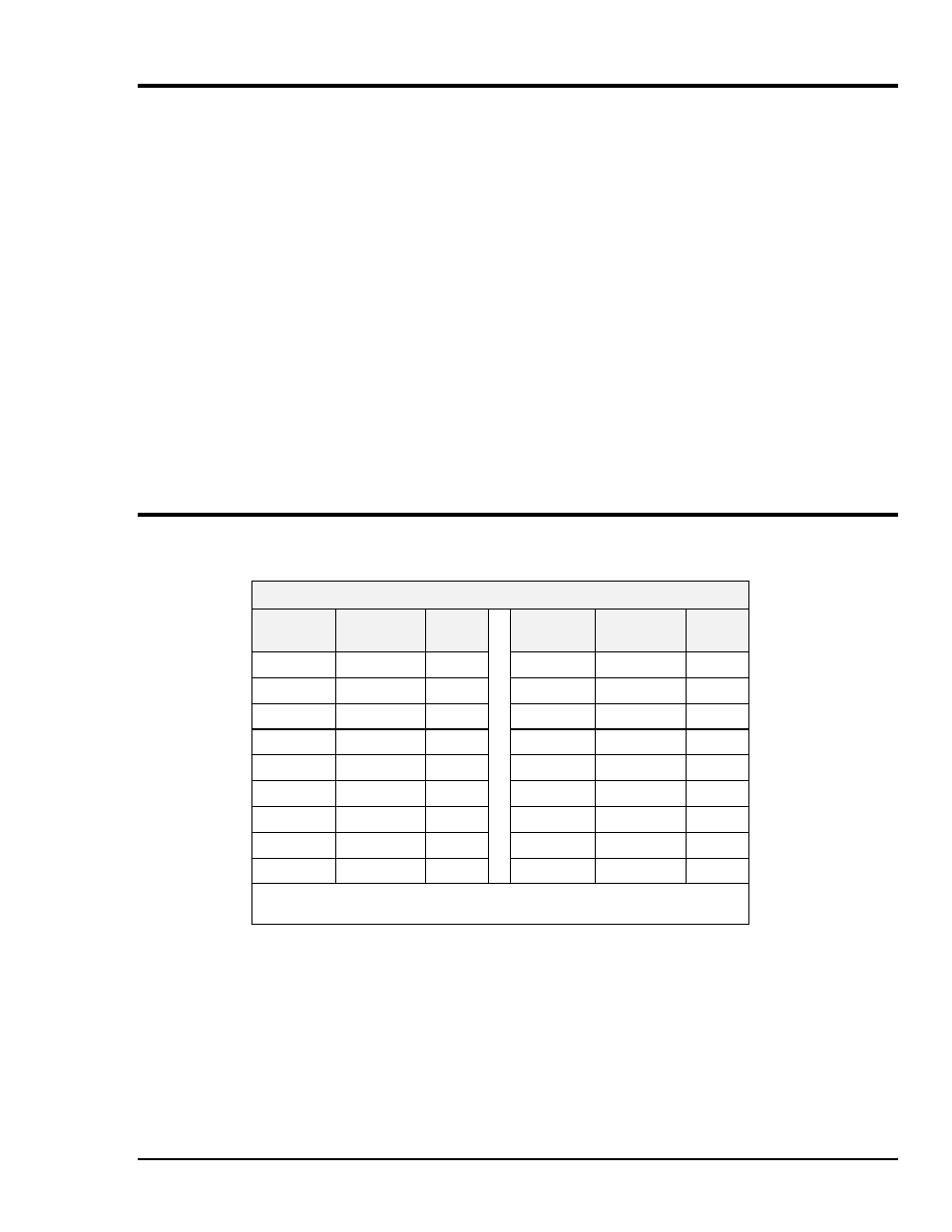
Divisor Latch Settings for Common Baud Rates
The following table lists divisor latch settings for common baud rates using a 1.8432 MHz input clock.
Divisor Latch Settings for Common Baud Rates
1
Desired
Baud Rate
Divisor
Latch Value
Error
2
Desired
Baud Rate
Divisor
Latch Value
Error
2
50
2304
---
2400
48
---
75
1536
---
3600
32
---
110
1047
0.026
4800
24
---
150
768
--
7200
16
---
300
384
---
9600
12
---
600
192
---
19200
6
---
1200
96
---
38400
3
---
1800
64
---
56000
2
2.86
2000
58
0.69
---
---
---
Note 1: Input clock used is 1.8432 MHz.
Note 2: Error is the error between “Desired” and “Actual” baud rate value.