Addressing – Measurement Computing COM232/8AT User Manual
Page 4
4 COM232/8AT User’s Guide
March 1998
1000-0901, rev 1.1
Addressing
The COM232/8AT uses eight I/O address locations per port. Full 16-bit address decoding allows base
address selections in the range: 0000 to FFFF Hex. Two DIP switches, designated SW1 and SW2, are
used to specify the adapter’s base address as follows:
• SW1 determines the address setting for A15 through A10.
• SW2 determines the address setting for A9 through A6.
The adapter uses the remaining address inputs to determine the channel and register being used.
The address of each port is incremented by a factor of
8 (in hexadecimal code) from the base address. For
this reason, 64 address locations are used, as indicated
by the table at the right. Note that SW1, SW2, and
other component locations can be referenced on the
figure, COM232/8AT Layout Reference, on page 6.
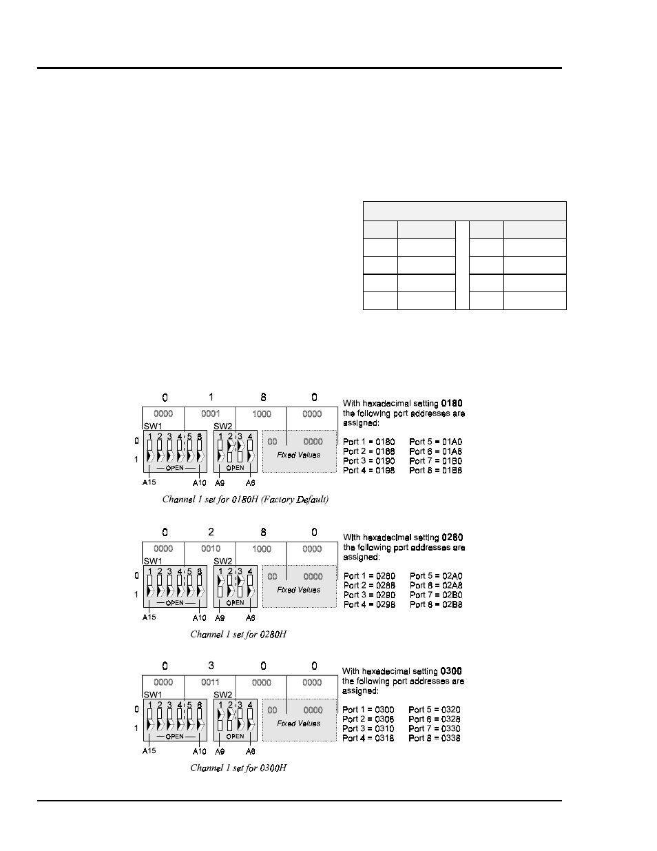
The following three figures serve as sample switch settings. Note that there are 6 “hidden” settings,
each with a fixed value of zero. These hidden settings have been included in the following illustrations.
64 Address Locations
Port
Range
Port
Range
1
0
thru
7
5
32
thru
39
2
8
thru
15
6
40
thru
47
3
16
thru
23
7
48
thru
55
4
24
thru
31
8
56
thru
63