Supply current, Voltage drop, Supply current -7 – Measurement Computing USB-PDISO8 User Manual
Page 17: Voltage drop -7, Power limitations us es, Ing multiple usb-pdiso8 devic
USB-PDISO8 User's Guide
Functional Details
2.
e.
3.
For each additional module you want to add, repeat steps 1-2, with the module you just daisy chained now
An
Power limitations us
es
When daisy chaining additional Measurement Computing USB products to the USB-PDISO8, you must ensure
powered with a 9 VDC
nominal, 1.0 A external power supply.
,
SO8 with all relays "on" draws 820 mA from the 1 A supply. When using the USB-
d conditions, you cannot daisy chain additional Measurement Computing USB products
unless you supply external power to each board in the chain.
ct.
curs with each board connected in a daisy chain system. The voltage drop between the
ly input and the daisy chain output is 0.5 V maximum. Factor in this voltage drop when you
configure a daisy chain system to ensure that at least 6.5 VDC is provided to the last board in the chain. Always
Connect the
USB OUT
connector on the connected module to the
USB IN
connector on the new modul
being the connected module.
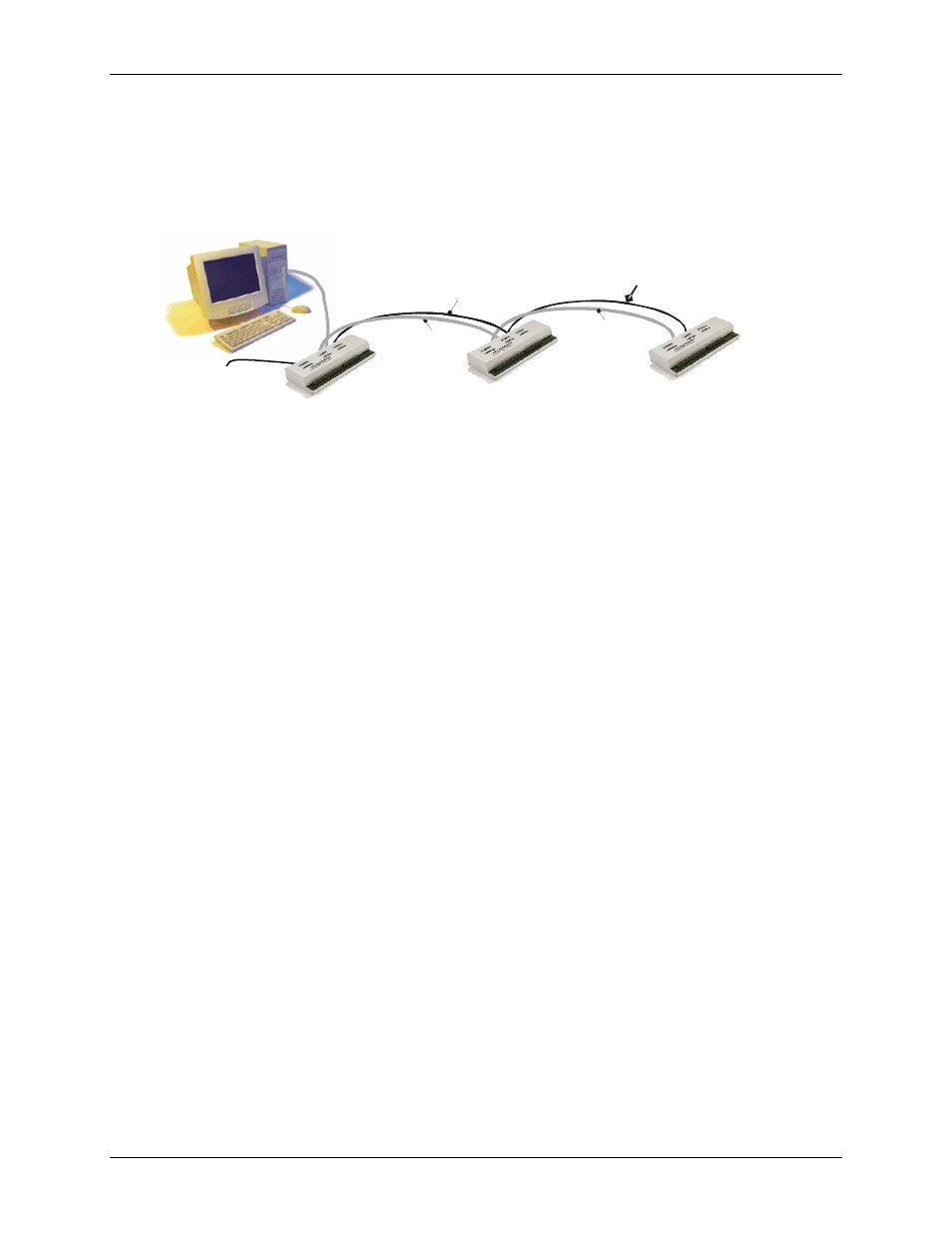
example of a daisy chain system is shown in Figure 3-9.
Figure 3-9. USB-PDISO8 daisy-chain connections
USB OUT to
USB IN
POWER OUT
to POWER IN
CB
-
PWR
-
9
power supply
to POWER IN
to POWER IN
USB IN
ing multiple USB-PDISO8 devic
that you provide adequate power to each board that you connect. The USB-PDISO8 is
When connecting multiple modules, power supplies with higher current capability, such as the CB PWR-9V3A
are available from MCC.
Supply current
Running one USB-PDI
PDISO8 under full loa
If you are not sure how much current your application requires, we recommend that you provide separate power
to each Measurement Computing USB product that you conne
Voltage drop
A drop in voltage oc
module power supp
provide a separate power supply when the USB-PDISO8 is the last board in the chain.
USB IN
USB port to
POWER OUT
USB OUT to
3-7