Extending the input range, Figure 3-7 – Measurement Computing USB-PDISO8 User Manual
Page 16
USB-PDISO8 User's Guide
Functional Details
IP4A
IP4B
NC
NO
C
+9 V
Figure 3-7. Schematic of battery-to-relay connection
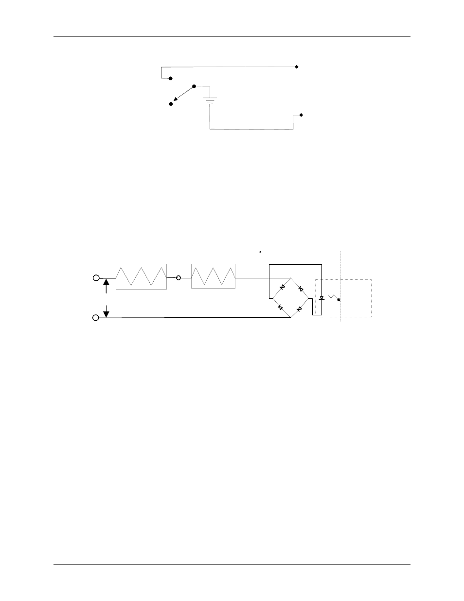
Extending the input ran
ond the 5 to 30 V specified by adding an external resistor. Figure 3-8 shows
the external resistor (R
ext
).
in
– 30)
calculates the resistor value for a given V
in
.
nput. Calculate the power
requirement in watts (P
w
) using the equation P
w
= R
ext
/10000
.
ge
You can extend the input range bey
The equation R
ext
= 100 * (V
Make sure the external resistor is capable of handling the power generated by the i
1.6 K
R
ext
V
in
R
ext
= 100 * (V
in
– 30)
P
w
= R
ext
/10000
Figure 3-8. External resistor added to extend the input range
Daisy chaining additional modules to the USB-PDISO8
the high-speed hub on
SB products to a single
bit rate of
12 Mb/s. The throughput rate is shared by all devices connected to the USB bus. Use the supplied cable or an
s procedure assumes you
already have one USB-PDISO8 connected to a computer and to the external power source. The USB-PDISO8
aisy-
.
Connect the
Power OUT
connector on the connected module to the
POWER IN
connector on the new
module.
Daisy chained Measurement Computing USB products connect to the USB bus through
the USB-PDISO8. You can daisy chain a maximum of four Measurement Computing U
USB 2.0 port on your computer, or a maximum of two devices to a single USB 1.1 port. Use the supplied cable
or an equivalent cable for daisy chaining to additional Measurement Computing USB products.
Measurement Computing USB products are USB 2.0 full-speed devices that provide a signaling
equivalent cable when daisy chaining Measurement Computing USB products.
To daisy-chain two or more USB-PDISO8 modules, follow the steps below. Thi
already connected to the computer is referred to as the connected module. The USB-PDISO8 you want to d
chain to the connected module is referred to as the new module.
1
3-6