Measurement Computing USB-PDISO8 User Manual
Page 15
USB-PDISO8 User's Guide
Functional Details
Differential isolated digital input terminals (IP0A to IP7B)
Connect up to eight isolated digital input signals using the following screw terminal pairs:
Input 0 terminal A and input 0 terminal B (IP0A and IP0B)
Input 1 terminal A and input 1 terminal B (IP1A and IP1B)
Input 2 terminal A and input 2 terminal B (IP2A and IP2B)
Input 3 terminal A and input 3 terminal B (IP3A and IP3B)
Input 4 terminal A and input 4 terminal B (IP4A and IP4B)
Input 5 terminal A and input 5 terminal B (IP5A and IP5B)
Input 6 terminal A and input 6 terminal B (IP6A and IP6B)
Input 7 terminal A and input 7 terminal B (IP7A and IP7B)
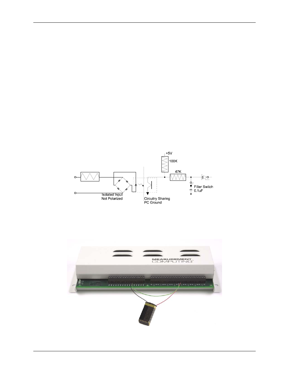
A schematic of a single channel is shown in
. Each signal is applied to a bridge rectifier so that the
input is not polarity-sensitive. Each input channel can be driven by either AC (50 - 1000 Hz) or DC voltage.
Figure 3-5. USB-PDISO8 single-channel configuration
The eight optically isolated (500 V) inputs can be read back as a single byte. Each input has a software-
controlled filter with a time constant of 5 ms (200 Hz). The filter is required for AC inputs, and recommended
for almost all DC inputs. Unless you have a good reason to turn off a filter, we recommend that you enable it.
You can enable and disable (default) each input filter using InstaCal's
Configure…
option.
1.6 K
Figure 3-6 illustrates a simple connection from a +9 V battery to the relay 4 terminals. When the relay is
energized, the relay 4 NO terminal connects the battery voltage to the input 4 terminal (IP4B).
Figure 3-6. Simple battery-to relay connection
Figure 3-7 shows the schematic of this connection.
3-5