Wire gauge, Form c relay output – Measurement Computing USB-PDISO8 User Manual
Page 14
USB-PDISO8 User's Guide
Functional Details
Table 3-4. Screw terminal pin out
Pin
Signal Name
Pin
Signal Name
IP0A
Input 0 terminal A
IP4A
Input 4 terminal A
IP0B
Input 0 terminal B
IP4B
Input 4 terminal B
IP1A
Input 1 terminal A
IP5A
Input 5 terminal A
IP1B
Input 1 terminal B
IP5B
Input 5 terminal B
IP2A
Input 2 terminal A
IP6A
Input 6 terminal A
IP2B
Input 2 terminal B
IP6B
Input 6 terminal B
IP3A
Input 3 terminal A
IP7A
Input 7 terminal A
IP3B
Input 3 terminal B
IP7B
Input 7 terminal B
0-NC
Relay 0 Normally Closed contact
4-NC
Relay 4 Normally Closed contact
0-C
Relay 0 Common contact
4-C
Relay 4 Common contact
0-NO
Relay 0 Normally Open contact
4-NO
Relay 4 Normally Open contact
1-NC
Relay 1 Normally Closed contact
5-NC
Relay 5 Normally Closed contact
1-C
Relay 1 Common contact
5-C
Relay 5 Common contact
1-NO
Relay 1 Normally Open contact
5-NO
Relay 5 Normally Open contact
2-NC
Relay 2 Normally Closed contact
6-NC
Relay 6 Normally Closed contact
2-C
Relay 2 Common contact
6-C
Relay 6 Common contact
2-NO
Relay 2 Normally Open contact
6-NO
Relay 6 Normally Open contact
3-NC
Relay 3 Normally Closed contact
7-NC
Relay 7 Normally Closed contact
3-C
Relay 3 Common contact
7-C
Relay 7 Common contact
3-NO
Relay 3 Normally Open contact
7-NO
Relay 7 Normally Open contact
Relay contact terminals (0 - NC, C, N0 through 7- NC, C, N0)
Connect external devices to the relay contacts using the USB-PDISO8 board's 24 screw terminals. Each relay
has a normally closed (NC), common (C), and normally open (NO) contact.
Caution!
Before connecting wires to the screw terminals, turn off the power to the USB-PDISO8, and make
sure that the signal wires do not contain live voltages.
Wire gauge
Use 12 AWG to 22 AWG wire to connect field devices. Properly insulate the wires to avoid any short circuit to
the other connections, ground, or other points on the board.
Caution!
Keep the length of stripped wire at a minimum to avoid a short to the enclosure!
When
connecting your field wiring to the screw terminals, use the strip gage on the terminal strip, or strip
to 5.5 - 7.0 mm (0.215" to 0.275") long.
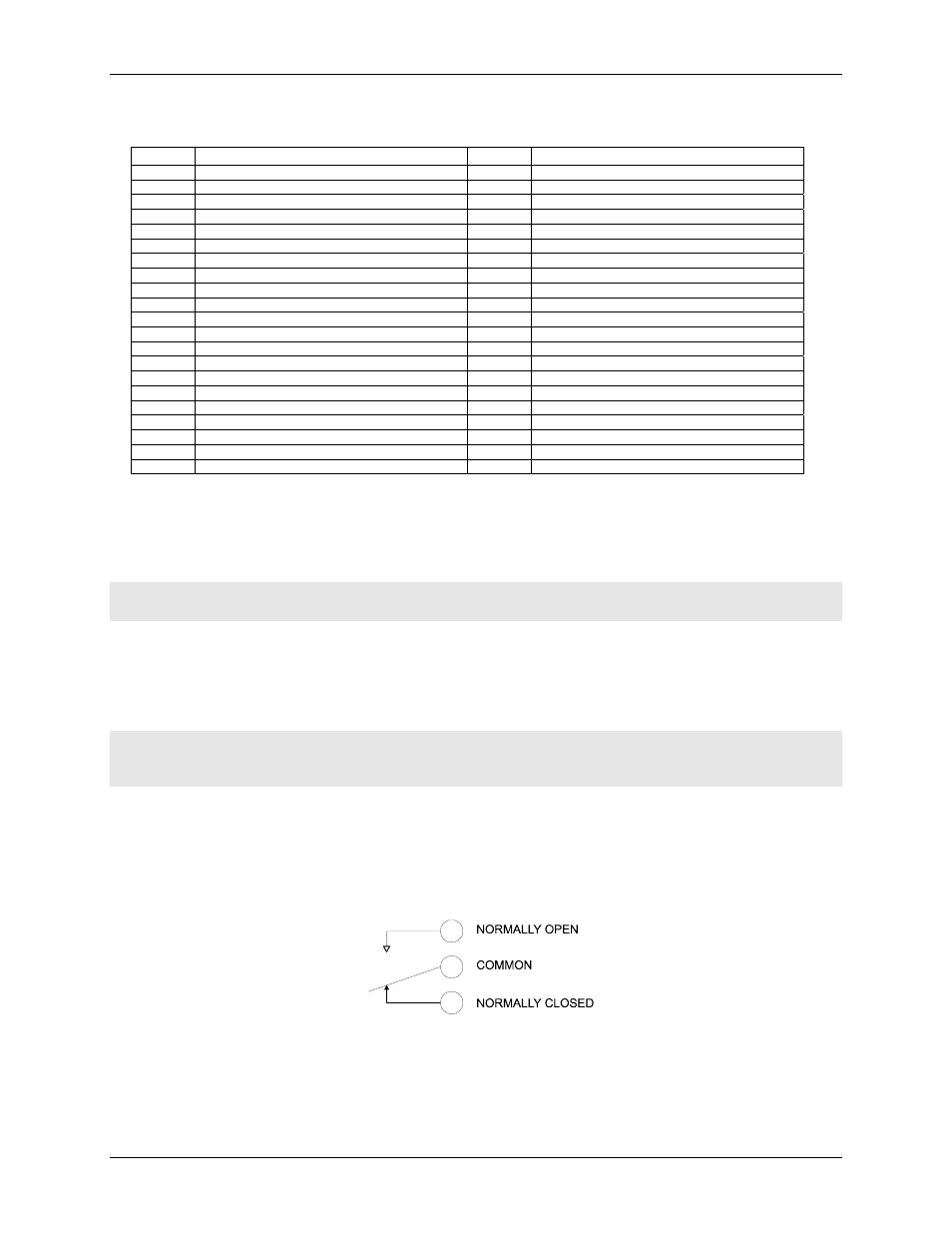
Form C relay output
A schematic for Form C relay contacts is shown in
. The Form C relay has a C, NO, and NC contact.
Figure 3-4. Form C SPDT relay
When a (0) is written to the output bit, the C and NC are in contact.
When a (1) is written to the output bit, the C and NO are in contact.
3-4