Oem connector and pinout (p4), Trigger/sync connector and pinout (p5) – Measurement Computing USB-7204 User Manual
Page 29
USB-7204 User's Guide
Specifications
29
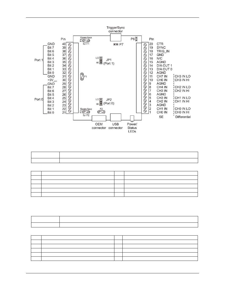
OEM connector and pinout (P4)
Table 25. OEM connector specifications
Parameter
Specification
Connector type
10 position 2.54 mm (0.1 in.) box header
Table 26. OEM connector pinout
Pin
Signal Name
Pin
Signal Name
1
N/C
2
V
BUS
(fuse protected)
3
N/C
4
D–
5
N/C (do not connect anything to this pin)
6
D+
7
N/C (do not connect anything to this pin)
8
GND
9
N/C (do not connect anything to this pin)
10
SHIELD
Trigger/Sync connector and pinout (P5)
Table 27. Trigger/Sync connector specifications
Parameter
Specification
Connector type
10 position 2.54 mm (0.1 in.) box header
Table 28. Trigger/Sync connector pinout
Pin
Signal Name
Pin
Signal Name
1
TRIG_IN
2
GND
3
N/C
4
GND
5
SYNC
6
GND
7
N/C
8
GND
9
N/C
10
N/C
- ACC-300 (7 pages)
- AI-EXP32 (20 pages)
- AI-EXP48 (19 pages)
- BTH-1208LS (30 pages)
- 6K-ERB08 (32 pages)
- BTH-1208LS Quick Start (4 pages)
- 6K-SSR-RACK08 (33 pages)
- BTH-1208LS-OEM (27 pages)
- CB-COM-Digital (68 pages)
- CB-7018 (68 pages)
- CB-7000 Utilities (44 pages)
- CB-7080D (74 pages)
- CB-COM-7033 (44 pages)
- CB-COM-7017 (72 pages)
- CB-COM-7024 (76 pages)
- CB-NAP-7000P (36 pages)
- CIO-DAC02/16 (16 pages)
- CIO-DAC02 (18 pages)
- CB-NAP-7000D (56 pages)
- CIO-DAC16-I (16 pages)
- CIO-DAC16/16 (20 pages)
- CIO-DAS08 (21 pages)
- CIO-DAC16 (20 pages)
- CIO-DAS08/JR (16 pages)
- CIO-DAS08/JR/16 (14 pages)
- CIO-DAS08/JR-AO (16 pages)
- CIO-DAS08-AOM (32 pages)
- CIO-DAS08-PGM (28 pages)
- CIO-DAS16/330 (34 pages)
- CIO-DAS48-I (17 pages)
- CIO-DAS16/M1 (38 pages)
- CIO-DAS48-PGA (18 pages)
- CIO-DAS800 (20 pages)
- CIO-DAS802/16 (22 pages)
- CIO-DAS6402/16 (40 pages)
- CIO-DAS-TEMP (20 pages)
- CIO-DDA06/16 (18 pages)
- CIO-DDA06/JR (17 pages)
- CIO-DIO24/CTR3 (21 pages)
- CIO-DIO24H (20 pages)
- CIO-DI192 (24 pages)
- CIO-DDA06 (21 pages)
- CIO-DIO48 (19 pages)
- CIO-DO192H (16 pages)
- CIO-DIO192 (20 pages)