Signal connections, Analog input, Single-ended configuration – Measurement Computing USB-7204 User Manual
Page 13: Differential configuration, Figure 4
USB-7204 User's Guide
Functional Details
13
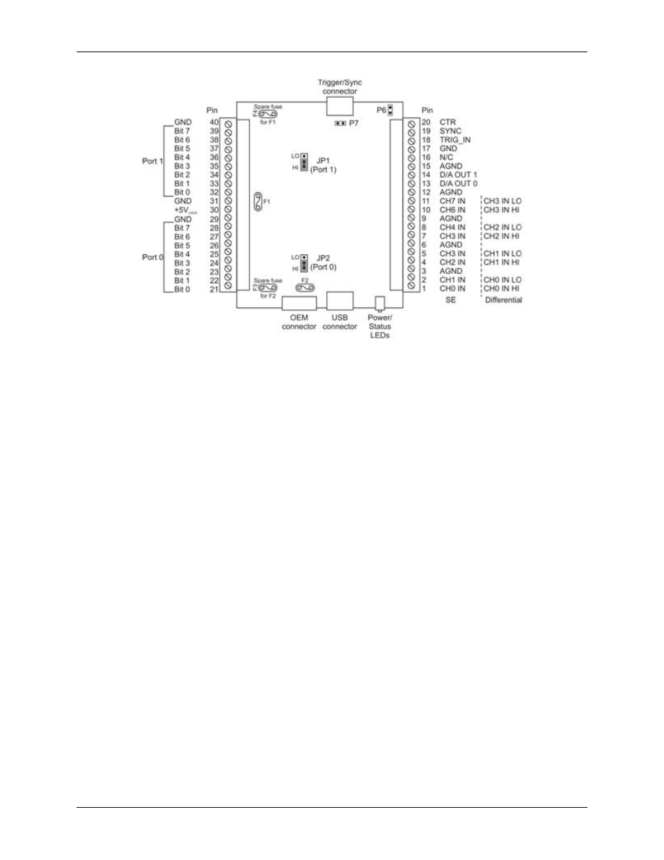
Figure 4. Screw terminal pinout
Signal connections
Analog input
You can connect up to eight analog input connections to the screw terminal containing pins 1 to 20 (
CH0
IN
through
CH7
IN
.) Refer to Figure 4 above for the location of the analog input pins.
You can configure the analog input channels as eight single-ended channels or four differential channels. By
default, differential mode is configured at power-up.
Single-ended configuration
When configured for single-ended mode, each analog input has 11-bit resolution, due to restrictions imposed by
the A/D converter. With single-ended mode, the input signal is referenced to signal ground and delivered
through two wires:
The wire carrying the signal to be measured connects to CH# IN.
The second wire connects to AGND.
The input range for single-ended mode is ±10 V.
Single-ended measurements using differential channels
To perform a SE measurement using differential channels, connect the signal to the "CH# IN HI" input, and
ground the associated "CH# IN LO" input.
Differential configuration
When configured for differential mode, each analog input has 12-bit resolution. In differential mode, the input
signal is measured with respect to the low input and delivered through three wires:
The wire carrying the signal to be measured connects to CH0 IN HI, CH1 IN HI, CH2 IN HI, or
CH3 IN HI.
The wire carrying the reference signal connects to CH0 IN LO, CH1 IN LO, CH2 IN LO, or
CH3 IN LO.
The third wire connects to GND.