Measurement Computing USB-7204 User Manual
Page 14
USB-7204 User's Guide
Functional Details
14
A low-noise precision programmable gain amplifier (PGA) is available on differential channels to provide gains
of up to 20 and a dynamic range of up to 12-bits. Differential mode input voltage ranges are ±20 V, ±10 V,
±5 V, ±4 V, ±2.5 V, ±2.0 V, ±1.25 V, and ±1.0 V.
In differential mode, the following two requirements must be met for linear operation:
Any analog input must remain in the
−10V to +20V range with r espect to ground at all times.
The maximum differential voltage on any given analog input pair must remain within the selected voltage
range.
The input [common-mode voltage + signal] of the differential channel must be in the
−10 V to +20 V range in
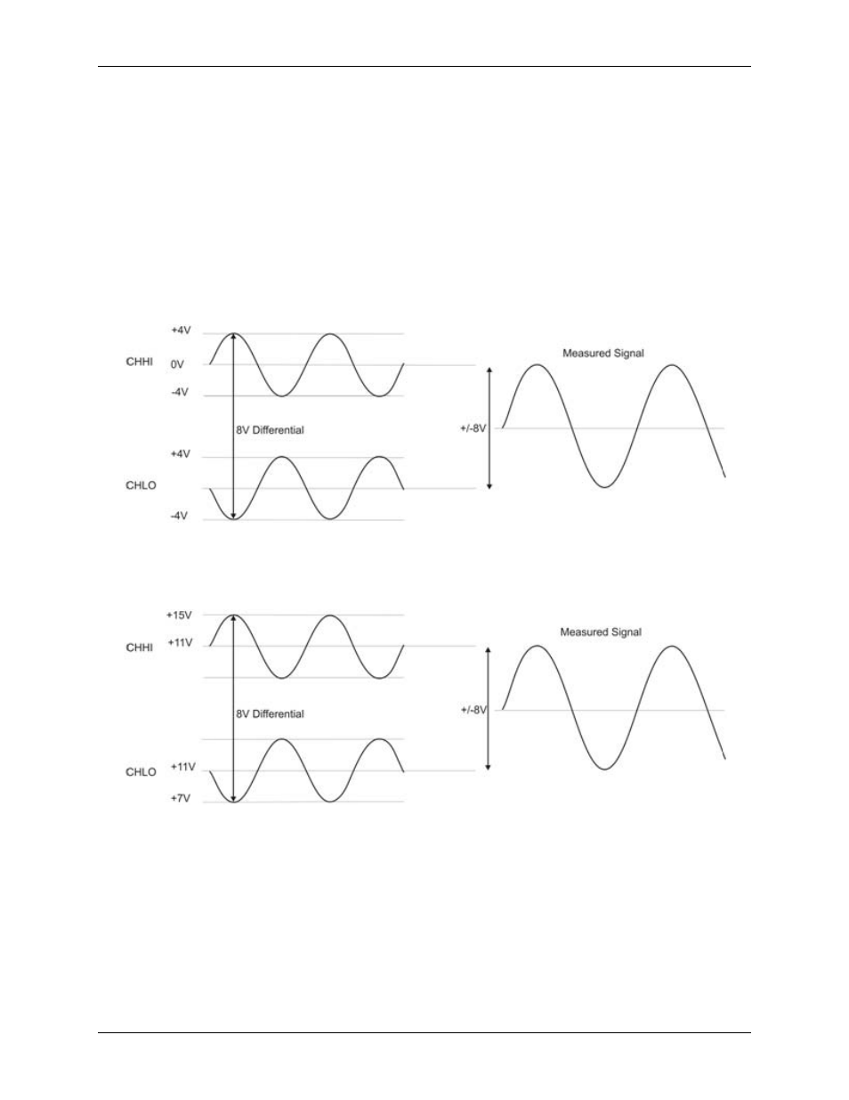
order to yield a useful result. For example, you input a 4 V pp sine wave to CHHI, and apply the same sine
wave 180° out of phase to CHLO. The common mode voltage is 0 V. The differential input voltage swings from
4 V-(-4 V) = 8 V to -4 V-4 V = -8V. Both inputs satisfy the -10 V to +20 V input range requirement, and the
differential voltage is suited for the ±10 V input range (see Figure 5).
Figure 5. Differential voltage example: common mode voltage of 0 V
If you increase the common mode voltage to 11 V, the differential remains at ±8 V. Although the [common-
mode voltage + signal] on each input now has a range of +7 V to +15 V, both inputs still satisfy the –10 V to
+20 V input requirement (see Figure 6).
Figure 6. Differential voltage example: common mode voltage of 11 V
If you decrease the common-mode voltage to –7 V, the differential stays at ±8 V. However, the solution now
violates the input range condition of -10 V to +20 V. The voltage on each analog input now swings from –3 V
to –11 V. Voltages between –10 V and –3 V are resolved, but those below –10 V are clipped (see Figure 7).