Digital input/output, External trigger, External clock input/output – Measurement Computing USB-7204 User Manual
Page 24
USB-7204 User's Guide
Specifications
24
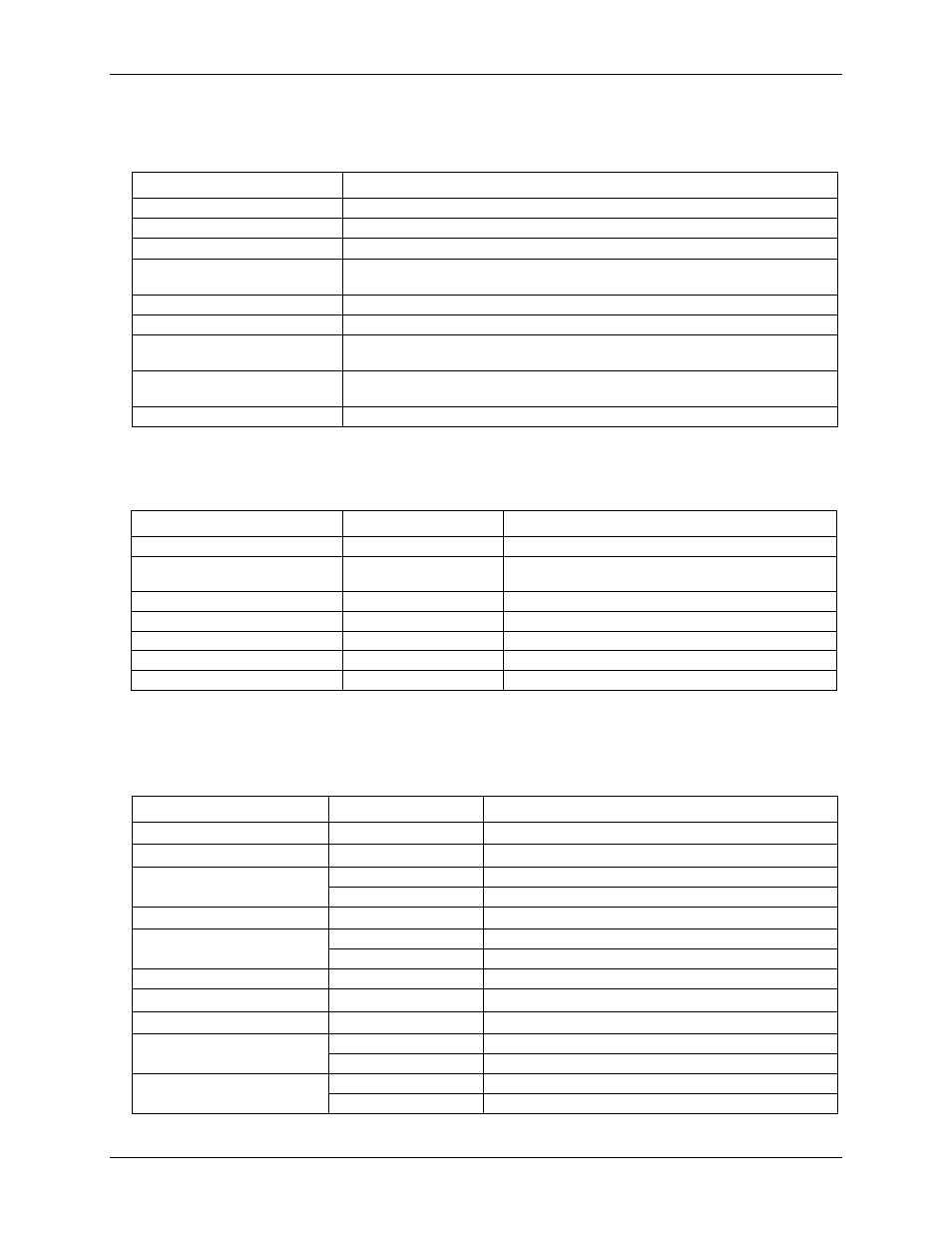
Digital input/output
Table 11. Digital I/O specifications
Parameter
Specification
Digital type
CMOS
Number of I/O
16 (Port 0 bit 0 through bit 7, Port 1 bit 0through bit 7)
Configuration
2 banks of 8
Pull up/pull-down configuration
All pins configurable via jumpers (JP1 and JP2) to Vs or Ground via 47 k resistors.
JP1 configures Port 1, and JP2 configures Port 0.
Input high voltage
2.0 V min, 5.5 V absolute max
Input low voltage
0.8 V max, –0.5 V absolute min
Output high voltage
(IOH = –2.5 mA)
3.8 V min
Output low voltage
(IOL = 2.5 mA)
0.7 V max
Power on and reset state
Input
External trigger
Table 12. Digital trigger specifications
Parameter
Conditions
Specification
Trigger source (Note 7)
External digital
TRIG_IN
Trigger mode
Software-selectable
Edge sensitive: user configurable for CMOS compatible
rising or falling edge.
Trigger latency
10 µs max
Trigger pulse width
1 µs min
Input high voltage
4.0 V min, 5.5 V absolute max
Input low voltage
1.0 V max, –0.5 V absolute min
Input leakage current
±1.0 µA
Note 7:
TRIG_IN is
a Schmitt trigger input protected with a 1.5 kΩ series resistor.
External clock input/output
Table 13. External clock I/O specifications
Parameter
Conditions
Specification
Pin name
SYNC
Pin type
Bidirectional
Software-selectable direction
Output (default)
Outputs internal A/D pacer clock.
Input
Receives A/D pacer clock from external source.
Input clock rate
50 KHz, max
Clock pulse width
Input mode
1 µs min
Output mode
5 µs min
Input leakage current
Input mode
±1.0 µA
Input high voltage
4.0 V min, 5.5 V absolute max
Input low voltage
1.0 V max, –0.5 V absolute min
Output high voltage (Note 8)
IOH = –2.5 mA
3.3 V min
No load
3.8 V min
Output low voltage (Note 8)
IOL = 2.5 mA
1.1 V max
No load
0.6 V max
Note 8:
SYNC is a Schmitt trigger input and is over-
current protected with a 1.5 kΩ series resistor.