Channel gain queue, Synchronized operations, N figure 12 – Measurement Computing USB-7204 User Manual
Page 19: Figure 12
USB-7204 User's Guide
Functional Details
19
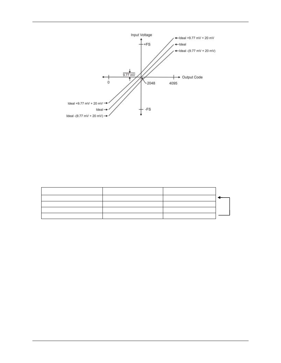
Figure 12. Error band plot
Channel gain queue
Use the device's channel gain queue to set up a scan sequence with a unique per-channel gain setting and
channel sequence. The queue is large enough for up to 16 channel configurations limited to either single-ended
or differential mode.
The channel gain queue feature removes the restriction of using an ascending channel sequence at a fixed gain.
This feature creates a channel list which is written to local memory on the USB-7204. The channel list is made
up of a channel number and range setting. An example of a four-element list is shown in the table below.
Sample channel gain queue list
Element
Channel
Range
0
CH0
BIP10V
1
CH0
BIP5V
2
CH7
BIP10V
3
CH2
BIP1V
When a scan begins with the gain queue enabled, the USB-7204 reads the first element, sets the appropriate
channel number and range, and then acquires a sample. The properties of the next element are then retrieved,
and another sample is acquired. This sequence continues until all elements in the gain queue have been selected.
When the end of the channel list is detected, the sequence returns to the first element in the list.
This sequence repeats until the specified number of samples is gathered. You must carefully match the gain to
the expected voltage range on the associated channel — otherwise, an over range condition can occur. Although
this condition does not damage the USB-7204, it does produce a useless full-scale reading. It can also introduce
a long recovery time from saturation, which can affect the next measurement in the queue.
Synchronized operations
You can connect the SYNC pin of two USB-7204 devices together in a master/slave configuration and acquire
data from the analog inputs of both devices using one clock. When the SYNC pin is configured as an output, the
internal A/D pacer clock is sent to the screw terminal. You can use this signal as a clock input to a second USB-
7204 by connecting it to the SYNC pin and Trig/SYNC connector of the second device.