Ground, Accuracy – Measurement Computing USB-7204 User Manual
Page 17
USB-7204 User's Guide
Functional Details
17
terminal. Measurement Computing highly recommends that you figure in a safety factor of 20% below this
maximum current loading for your applications. A conservative, safe user maximum in this case would be in the
350 mA to 375 mA range (fuse-rated).
Since laptop computers typically allow up to 100 mA, the USB-7204 in a fully-loaded configuration may be
above that allowed by the computer. In this case, you must determine the per-pin loading in the application to
ensure that the maximum loading criteria is met. The per-pin loading is calculated by simply dividing the +5 V
by the load impedance of the pin in question.
Ground
The analog ground (
AGND
) terminals provide a common ground for all analog channels. The digital ground
(
GND
) terminals provide a common ground for the digital, trigger, counter, and sync channels and the power
terminal.
Accuracy
The overall accuracy of any instrument is limited by the error components within the system. Quite often,
resolution is incorrectly used to quantify the performance of a measurement product. While "12-bits" or "1 part
in 4096" does indicate what can be resolved, it provides little insight into the quality of an absolute
measurement. Accuracy specifications describe the actual results that can be realized with a measurement
device.
There are three types of errors which affect the accuracy of a measurement system:
offset
gain
nonlinearity
The primary error sources in the USB-7204 are offset and gain. Nonlinearity is small in the USB-7204, and is
not significant as an error source with respect to offset and gain.
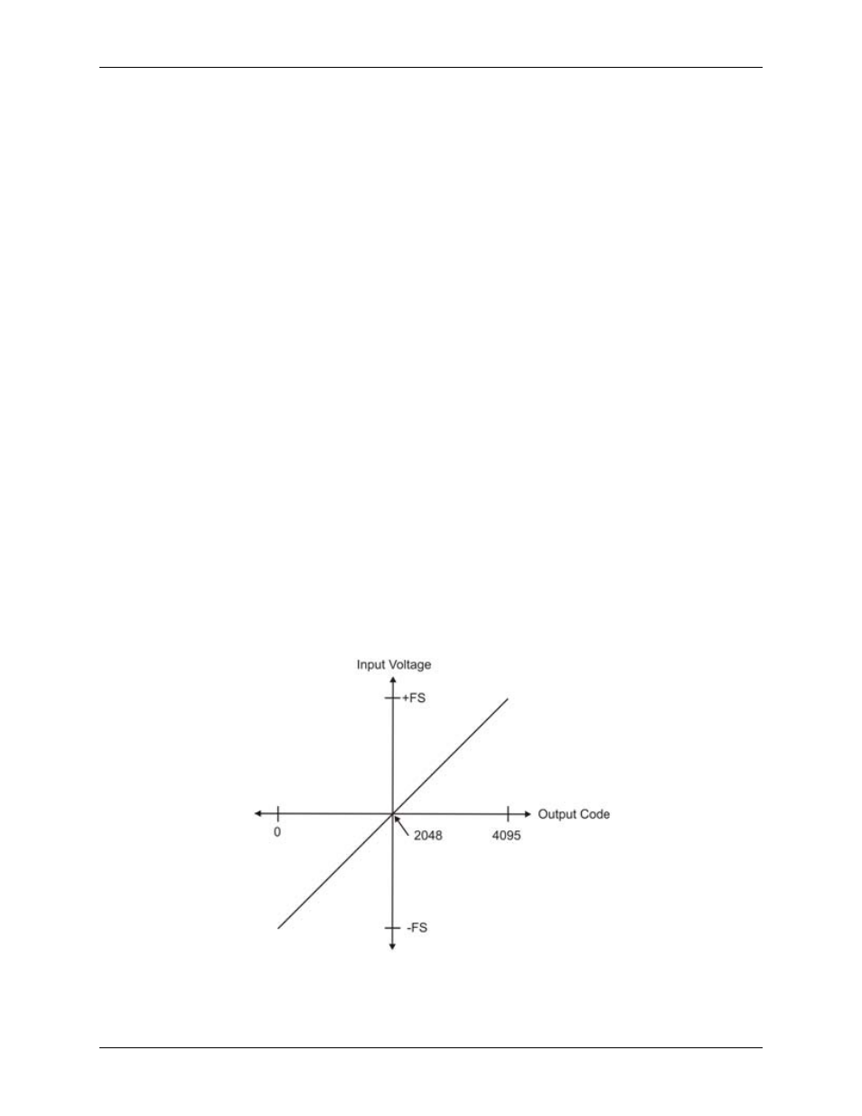
Figure 9 shows an ideal, error-free, USB-7204 transfer function. The typical calibrated accuracy of the USB-
7204 is range-dependent, as explained in the Specifications chapter on page 21. We use a ±10 V range here as
an example of what you can expect when performing a measurement in this range.
The accuracy plots in Figure 9 are drawn for clarity and are not drawn to scale.
Figure 9. Ideal ADC transfer function
The USB-7204 offset error is measured at mid-scale. Ideally, a zero volt input should produce an output code of
2048. Any deviation from this is an offset error. Figure 10 shows the USB-7204 transfer function with an offset