Analog output, Digital i/o, Pull up/down configuration – Measurement Computing USB-7204 User Manual
Page 15
USB-7204 User's Guide
Functional Details
15
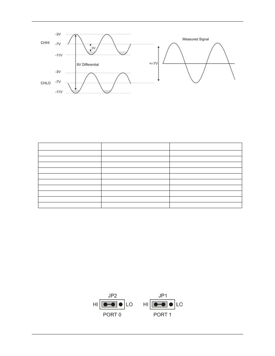
Figure 7. Differential voltage example: common mode voltage of –7 V
Since the analog inputs are restricted to a
−10 V to +20 V signal swing with respect to ground, all ranges except
±20 V can realize a linear output for any differential signal with zero common mode voltage and full scale
signal inputs. The ±20 V range is the exception. You cannot put
−20 V on CHHI and 0 V on CHLO since this
violates the input range criteria.
The table below shows some possible inputs and the expected results.
Sample inputs and differential results
CHHI
CHLO
Result
–20 V
0 V
Invalid
–15 V
+5 V
Invalid
–10 V
0 V
–10 V
–10 V
+10 V
–20 V
0 V
+10 V
–10 V
0 V
+20 V
-20 V
+10 V
–10 V
+20 V
+10 V
0 V
+10 V
+15 V
–5 V
+20 V
+20 V
0
+20 V
Analog output
You can connect up to two analog output connections to screw terminal pins 13 and 14 (
D/A OUT 0
and
D/A
OUT 1
). Each channel can be paced individually at rates up to 10,000 updates per second. Both channels can be
paced simultaneously using the same time base at 5000 updates per channel. The 0-4.096 V output range
provides a convenient 1 mV per LSB when setting the output voltage levels.
Digital I/O
The USB-7204 has two eight-bit ports (
Port 0
to
Bit 0
to
Bit 7
and
Port 1
to
Bit 0
to
Bit 7
). Each port is
configurable as either input or output.
Pull up/down configuration
The digital pins are configurable via jumpers for pull-up to USB +5 V (HI) or pull-down to ground (LO).
Jumper JP2 configures Port 0, and JP1 configures Port 1. On power up and reset the DIO pins are configured as
input and pulled by JP1/JP2.
Figure 8. Jumper JP0 and JP1 configuration