Usb connector, Oem connector, Trigger/sync connector – Measurement Computing USB-7204 User Manual
Page 11
USB-7204 User's Guide
Functional Details
11
USB connector
The USB connector provides +5 V power and communication. The voltage supplied through the USB connector
is system-dependent, and may be less than 5 V. No external power supply is required.
This connector operates in parallel with the OEM connector — do not connect to both the USB connector and
the OEM connector.
OEM connector
The OEM connector operates in parallel with the USB connector — do not connect to both the USB connector
and the OEM connector.
The OEM connector is a 0.1" box header. Pins 2, 4, 6, 8, and 10 provide a USB connection, as listed in the
connector pinout below:
OEM connector pinout
Pin
Signal Name
Pin
Signal Name
1
N/C
2
VBUS
3
N/C
4
D–
5
N/C (do not connect anything to this pin)
6
D+
7
N/C (do not connect anything to this pin)
8
GND
9
N/C (do not connect anything to this pin)
10
SHIELD
Modifications are required in order to use the OEM connector
We recommend that you return the device to the factory for this modification.
Should you have the capabilities to perform the modifications, the following change is required: to create a USB
connection via the OEM connector, locations R48 and R49 must be populated. We recommend that you
populate with 0603 size 0
Ω resistors or provide solder bridges to close the gaps.
Trigger/Sync connector
The Trigger/Sync connector provides two signals —
SYNC
and
TRIG_IN
. These signals are also available on
on page 16 for details about these signals).
Trigger/Sync connector pinout
Pin Signal Name
Pin Signal Name
1
TRIG_IN
2
GND
3
N/C
4
GND
5
SYNC
6
GND
7
N/C
8
GND
9
N/C
10
N/CD
Use a 0.1" box header when making connections to the Trigger/Sync connector.
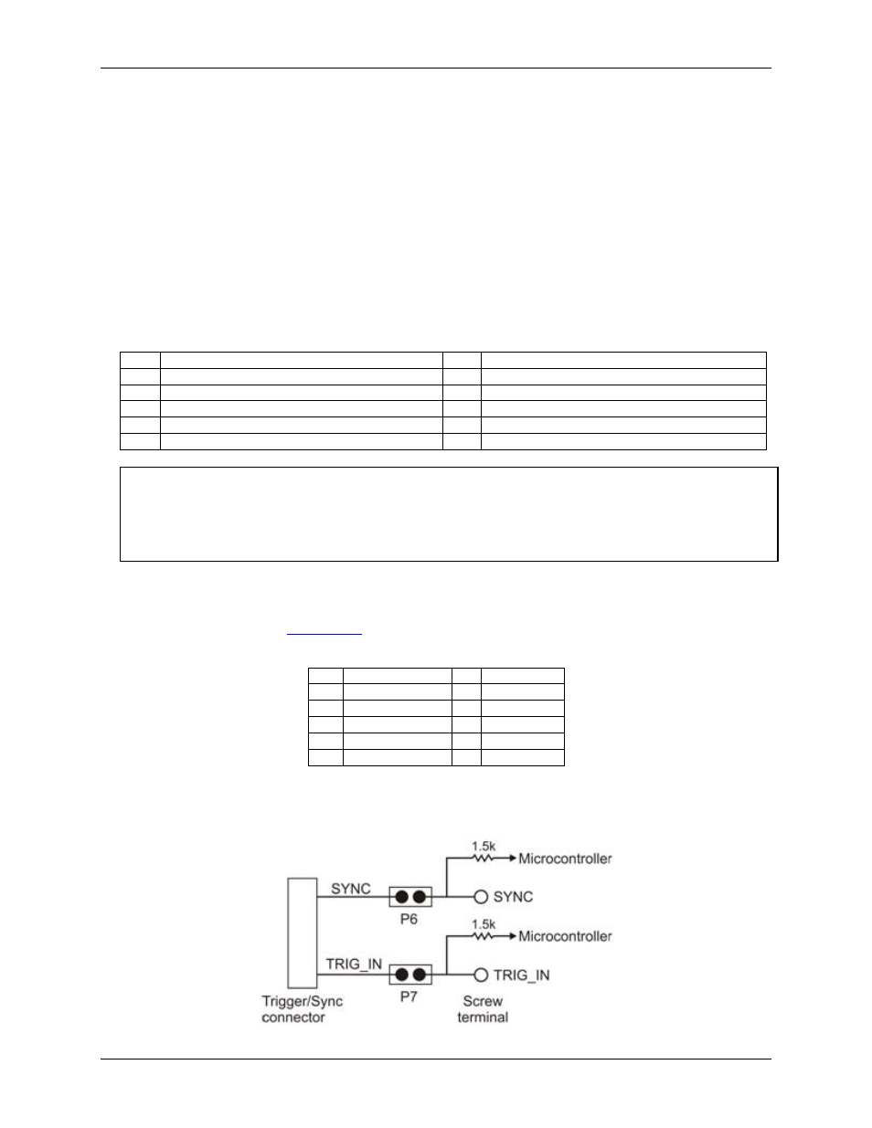
The Trigger/Sync connector internally connects its SYNC and TRIG_IN pins to the screw terminal via jumpers
P6
and
P7
.
Figure 3. Jumper P6 and P7 schematic