Specifications, Analog input, Chapter 4 – Measurement Computing USB-7204 User Manual
Page 21
21
Chapter 4
Specifications
All specifications are subject to change without notice.
Typical for 25°C unless otherwise specified.
Specifications in italic text are guaranteed by design.
Analog input
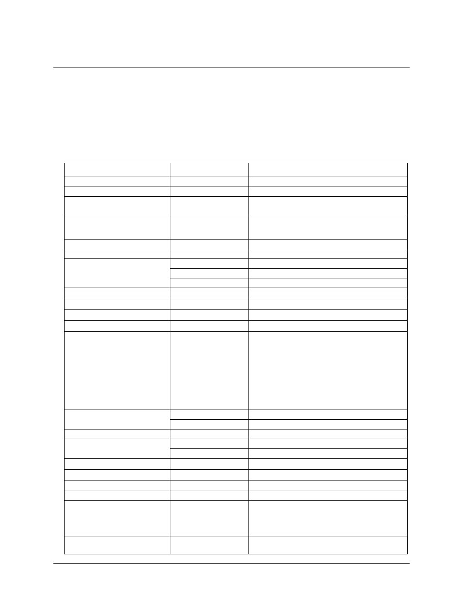
Table 1. Analog input specifications
Parameter
Conditions
Specification
A/D converter type
Successive approximation type
Input modes
Single-ended or differential (default)
Input voltage range for linear
operation, single-ended mode
CHx to GND
±10 volts (V) max
Input common-mode voltage range
for linear operation, differential
mode
CHx to GND
–10 V min, +20 V max
Absolute maximum input voltage
CHx to GND
±28 V max
Input impedance
122
kΩ
Input current (Note 1)
Vin = +10 V
70 microamperes (µA) typ
Vin = 0 V
–12 µA typ
Vin = –10 V
–94 µA typ
Number of channels
8 single-ended / 4 differential, software-selectable
Configuration
Single A/D
Sampling method
Multiplexed
Input ranges, single-ended mode
±10 V
G=2
Input ranges, differential mode
±20 V
G=1
±10 V
G=2 (default)
±5 V
G=4
±4 V
G=5
±2.5 V
G=8
±2.0 V
G=10
±1.25 V G=16
±1.0 V
G=20
Software-selectable
Throughput (Note 2)
Software paced
250 samples per second (S/s) typ, system dependent
Scan to system memory
0.596 to 50,000 S/s
Channel gain queue
Up to 16 elements
Software-selectable channel, range.
Resolution (Note 3)
Differential
12 bits, no missing codes
Single-ended
11 bits
Integral linearity error
±1 least significant bit (LSB) typ
Differential linearity error
±0.5 LSB typ
Repeatability
±1 LSB typ
Trigger source
Software-selectable
External digital: TRIG_IN
Pacer source
Software-selectable
Internal
External (SYNC), rising edge triggered
External Gated (SYNC), see Note 4
Programmed IO
Calibration
Factory Cal factors stored in firmware. Cal factors
must be applied via application software.