Screw terminal pinout, Differential mode pinout, Single-ended mode pinout – Measurement Computing USB-231 User Manual
Page 27
USB-231 User's Guide
Specifications
27
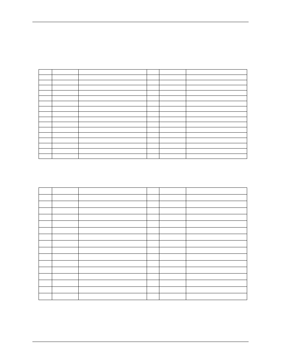
Screw terminal pinout
Differential mode pinout
Do not connect to terminal block pins labeled NC.
Table 15. Screw terminal pinout
Pin
Signal name
Pin description
Pin
Signal name
Pin description
1
AGND
Analog ground
17
DIO0
DIO bit 0
2
CH0H
Analog input 0 HI
18
DIO1
DIO bit 1
3
CH0L
Analog input 0 LO
19
DIO2
DIO bit 2
4
AGND
Analog ground
20
DIO3
DIO bit 3
5
CH1H
Analog input 1 HI
21
DIO4
DIO bit 4
6
CH1L
Analog input 1 LO
22
DIO5
DIO bit 5
7
AGND
Analog ground
23
DIO6
DIO bit 6
8
CH2H
Analog input 2 HI
24
DIO7
DIO bit 7
9
CH2L
Analog input 2 LO
25
NC
No connection
10
AGND
Analog ground
26
TRIG
Digital trigger input
11
CH3H
Analog input 3 HI
27
NC
No connection
12
CH3L
Analog input 3 LO
28
NC
No connection
13
AGND
Analog ground
29
CTR
Counter input
14
AOUT0
Analog output 0
30
GND
Digital ground
15
AOUT1
Analog output 1
31
+ VO
User voltage output
16
AGND
Analog ground
32
GND
Digital ground
Single-ended mode pinout
Do not connect to terminal block pins labeled NC.
Table 16. Screw terminal pinout
Pin
Signal name
Pin description
Pin
Signal name
Pin description
1
AGND
Analog ground
17
DIO0
DIO bit 0
2
CH0H
Analog input 0
18
DIO1
DIO bit 1
3
CH0L
Analog input 4
19
DIO2
DIO bit 2
4
AGND
Analog ground
20
DIO3
DIO bit 3
5
CH1H
Analog input 1
21
DIO4
DIO bit 4
6
CH1L
Analog input 5
22
DIO5
DIO bit 5
7
AGND
Analog ground
23
DIO6
DIO bit 6
8
CH2H
Analog input 2
24
DIO7
DIO bit 7
9
CH2L
Analog input 6
25
NC
No connection
10
AGND
Analog ground
26
TRIG
Digital trigger input
11
CH3H
Analog input 3
27
NC
No connection
12
CH3L
Analog input 7
28
NC
No connection
13
AGND
Analog ground
29
CTR
Counter input
14
AOUT0
Analog output 0
30
GND
Digital ground
15
AOUT1
Analog output 1
31
+ VO
User voltage output
16
AGND
Analog ground
32
GND
Digital ground