Differential configuration, Input range, Multichannel scanning – Measurement Computing USB-231 User Manual
Page 15
USB-231 User's Guide
Functional Details
15
Differential configuration
When configured for differential input mode, the input signal is measured with respect to the low input and
delivered through three wires:
Connect the wire carrying the signal to be measured to
CHxH
Connect the wire carrying the reference signal to
CHxL
Connect the third wire to
AGND
.
The differential mode pinout is shown in Figure 4 on page 12.
Note
: To perform a single-ended measurement using differential channels, connect the signal to
CHxH
and
ground the associated
CHxL
input.
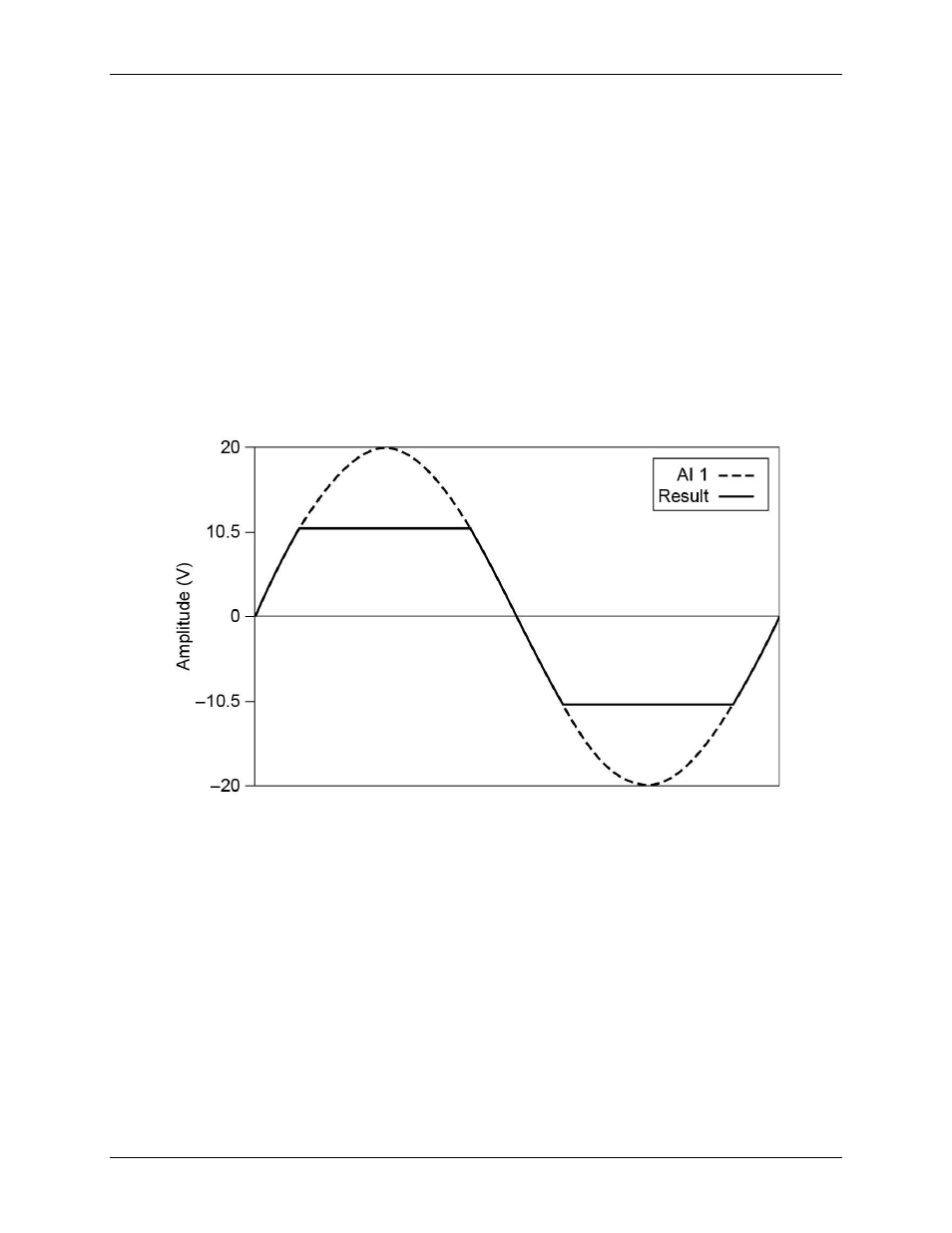
Input range
The USB-231 has an input range of ±10 V. For DIFF mode, each AI should stay within ±10 V with respect to
AGND, and the voltage between positive and negative inputs should be lower or equal to ±10 V. For SE mode,
signals of ±10 V at any analog input terminal with respect to AGND are accurately measured.
Beyond ±10 V, the input signal begins clipping as shown in Figure 7. Typically, this clipping begins at ±10.5 V.
Figure 7. Analog input exceeding ±10 V returning clipped results
Multichannel scanning
The USB-231 can scan multiple channels at high rates and digitize the signals accurately. However, you should
consider several issues when designing your measurement system to ensure the high accuracy of your
measurements:
Use low impedance sources –
To ensure fast settling times, your signal sources should have an
impedance of <1 kΩ. Large source impedances increase the settling time of the DAQ device and decrease
the accuracy at fast scanning rates.
Use short high-quality cabling –
Using short high-quality cables can minimize several effects that
degrade accuracy including crosstalk, transmission line effects, and noise. The capacitance of the cable also
can increase the settling time.
To ensure the specified EMC performance, operate this product only with shielded cables and accessories.
The length of any wire or cable
connected to the screw terminal connector must be no longer than 0.5 m (20 in.).
Avoid scanning faster than necessary –
Design your system to scan at slower speeds to give the DAQ
device more time to settle to a more accurate level when switching between channels.