Analog output – Measurement Computing USB-231 User Manual
Page 16
USB-231 User's Guide
Functional Details
16
Analog output
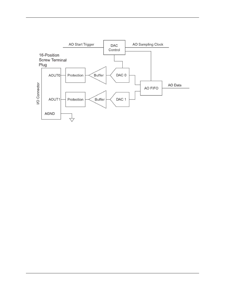
Figure 8 shows the USB-231 analog output circuitry.
Figure 8. USB-231 analog output circuitry
The main analog output circuitry blocks are as follows:
Protection –
The protection circuit prevents damage of the buffers in case of a short circuit or an
overvoltage condition.
Buffer –
The buffer amplifies the analog signal to the ±10 V range and ensures the driving capability for
the external load.
DAC 0 and DAC 1 –
The digital-to-analog converters (DAC) convert the digital signals into low-level
analog signals.
AO FIFO –
The AO FIFO (first-in-first out) ensures that data is transferred to the DACs in a timely manner
without being affected by USB latencies.
DAC Control –
The DAC control sets the DAC data rate and the startup condition, which could be
triggered by the
TRIG
signal.
Analog output signals are referenced to AGND. Connect the loads between AOUT0 or AOUT1 and AGND as
shown in .