Trigger input, Counter input, Vo power source – Measurement Computing USB-231 User Manual
Page 19: Connecting the load
USB-231 User's Guide
Functional Details
19
Trigger input
The
TRIG
terminal is an external digital trigger input. The trigger mode is software-selectable for rising edge- or
falling edge detection.
Counter input
The
CTR
terminal is a 32-bit counter that can count rising edges. Edges can only be counted up from 0.
Counting down is not supported – you cannot set the initial count to 100 and count down to 99, 98, 97.
+VO power source
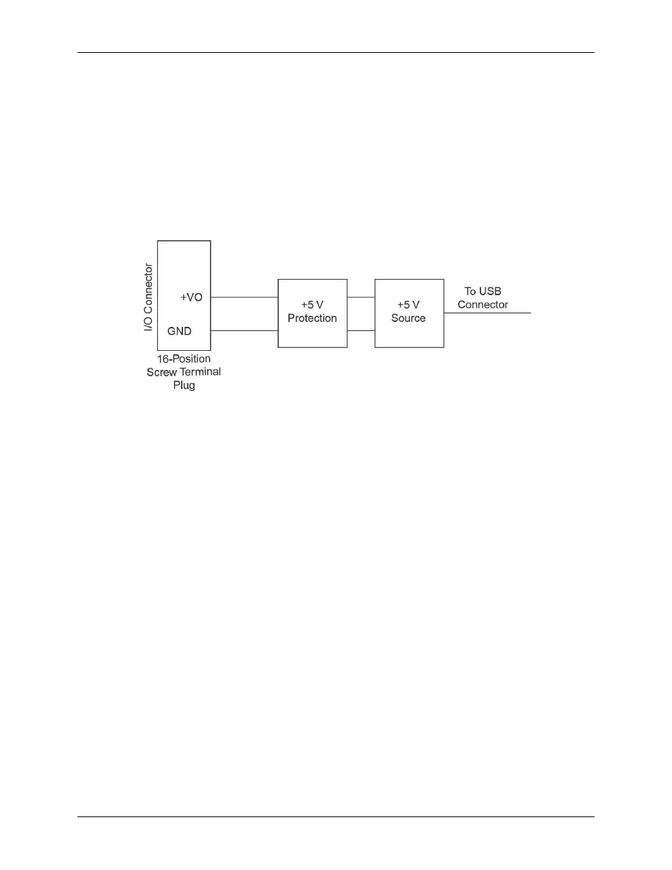
Figure 11 shows the
+VO
power source circuitry of the USB-231.
Figure 11. +VO power source circuitry
The main blocks featured in the
+VO
power source circuitry are as follows:
+5 V Source
—Regulated 5 V supply.
+5 V Protection
—Circuit for overvoltage, over current, and short circuit protection.
The +5 V source is limited at 200 mA typically. In case of hard short circuit to ground, this limit is further
reduced to avoid excessive power dissipation.
Connecting the load
The return terminal for the +5 V source is the
GND
terminal. The +5 V load should be connected between the
+VO
terminal and
GND
. The current delivered by the USB-231 at the
+VO
terminal is sourced from the USB
connector. To meet the USB specifications, a maximum of 150 mA can be used from the
+VO
terminal.