External components, Screw terminals – Measurement Computing USB-231 User Manual
Page 11
USB-231 User's Guide
Functional Details
11
External components
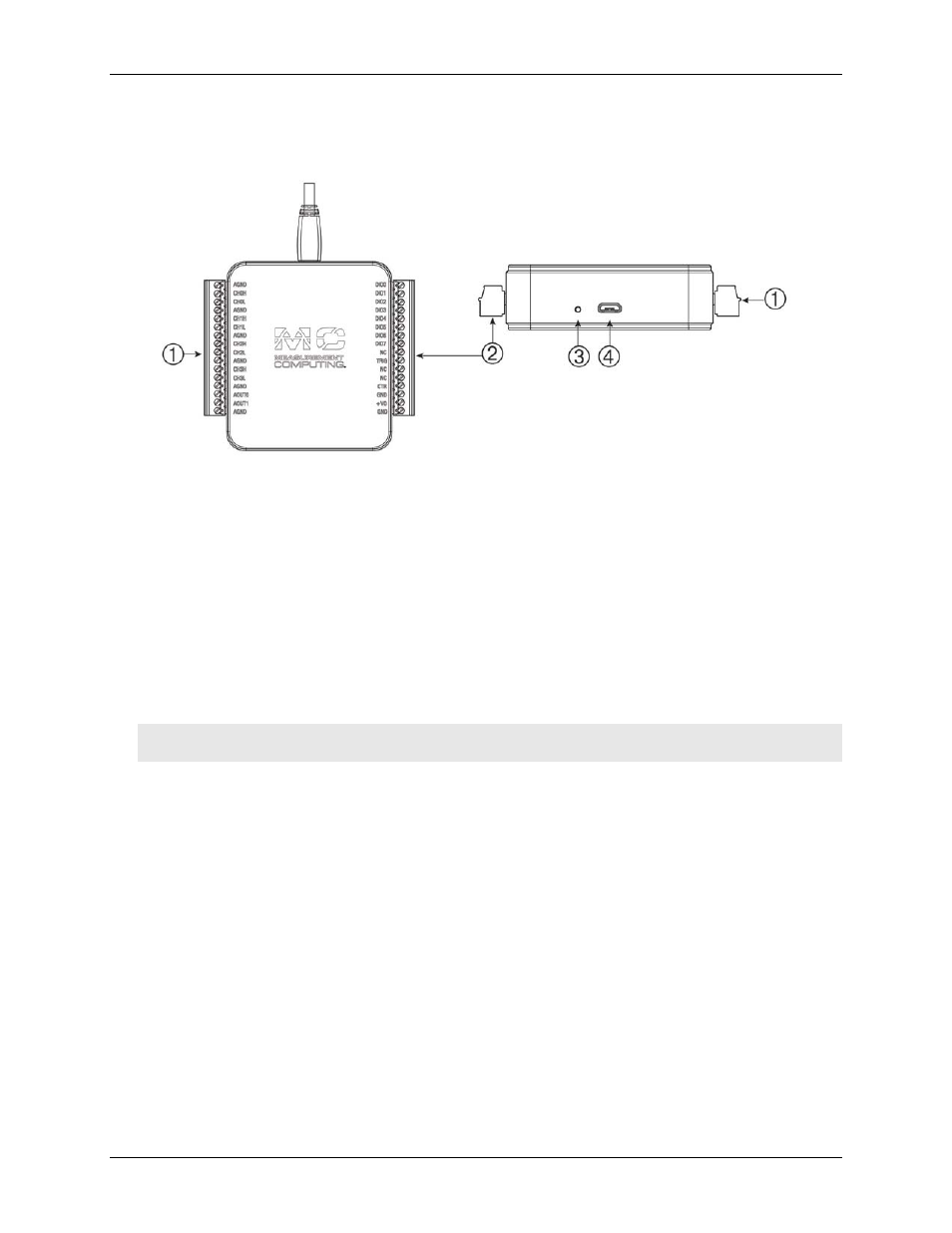
The external components on the USB-231 are shown in Figure 3.
1
Screw terminal pins 1 to 16
3
LED Indicator
2
Screw terminal pins 17 to 32
4
USB connector
Figure 3. USB-231 external components
Screw terminals
The screw terminals provide the following connections (refer to Figure 4 and Figure 5 for pinout diagrams):
Eight single-ended/four differential analog inputs (
CH0H/CH0L
to
CH3H/CH3L
)
Two analog outputs (
AOUT0
and
AOUT1
)
Digital trigger input (
TRIG
)
Counter input (
CTR
)
User voltage output
(+VO
)
Analog ground reference (
AGND
) and digital ground reference (
GND
)
Caution! To ensure the specified EMC performance, the length of any wire or cable connected to the screw
terminal connector must be no longer than 0.5 m (20 in.).