Digital input, Digital output, External digital trigger – Measurement Computing USB-231 User Manual
Page 24: Counter
USB-231 User's Guide
Specifications
24
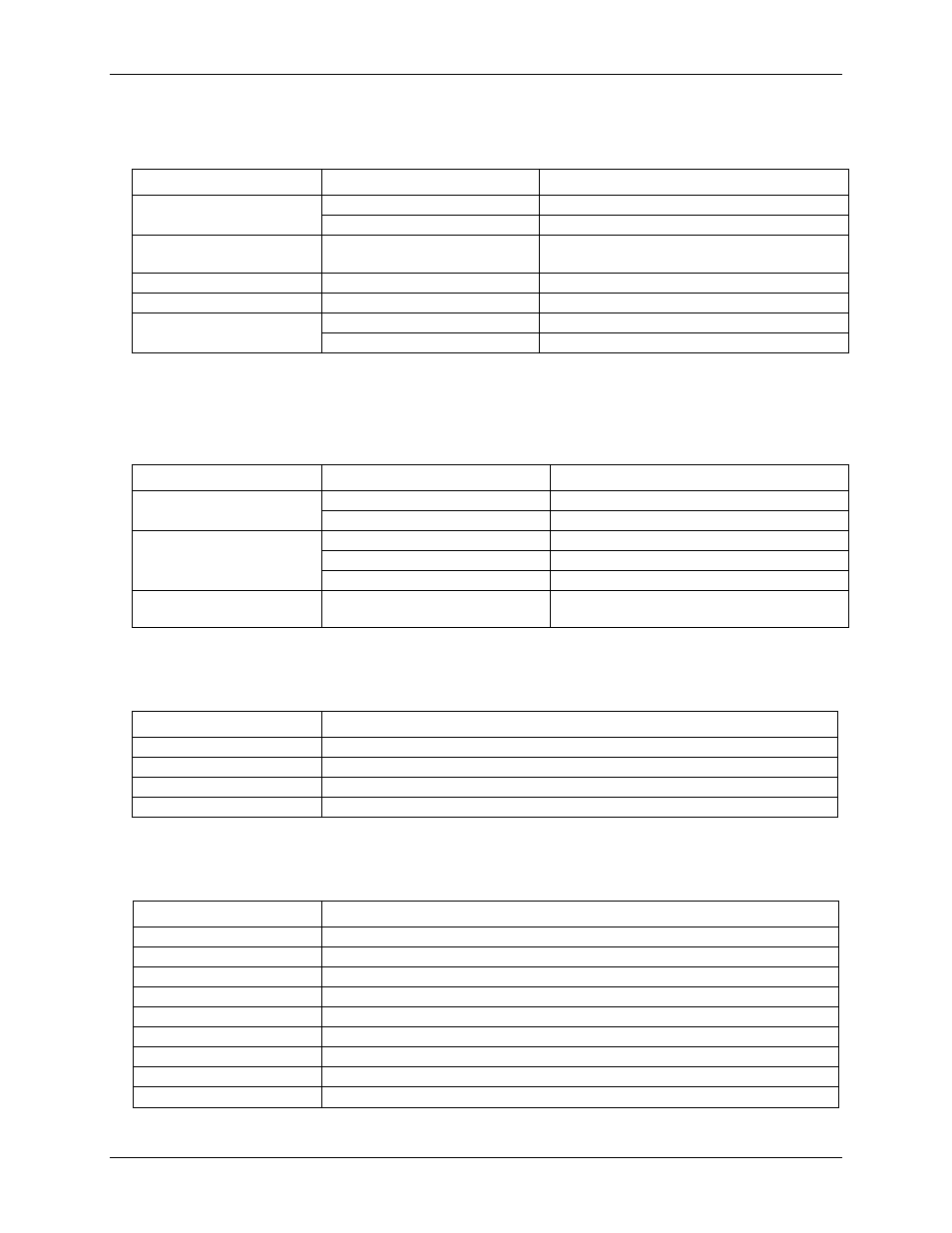
Digital input
Table 5. Digital input specifications
Parameter
Condition
Specification
Input voltage range
Power on
0 V to 5 V
Power off
0 V to 3.3 V (Note 1)
Input voltage protection
±20 V on two lines per port (maximum of five
lines for all ports) for up to 24 hours
Input high voltage
2.3 V min
Input low voltage
0.8 V max
Input leakage current
At 3.3 V
0.8 mA max
At 5 V
4.5 mA max
Note 1:
Do not leave a voltage above 3.3 V connected on the DIO line when the device is not powered. This
can cause long-term reliability issues.
Digital output
Table 6. Digital output specifications
Parameter
Condition
Specification
Output low voltage
4 mA
0.7 V max
1 mA
0.2 V max
Output high voltage
4 mA
2.1 V min
1 mA
2.8 V min
3.6 V max
Maximum output current per
line
±4 mA
External digital trigger
Table 6. External digital trigger specifications
Parameter
Specification
Trigger source
TRIG input
Trigger mode
Software configurable for rising or falling edge. Power on default is rising edge.
Input high voltage
2.3 V min
Input low voltage
0.8 V max
Counter
Table 7. Counter specifications
Parameter
Specification
Pin name
CTR
Number of counters
1
Resolution
32 bits
Counter type
Edge counter, rising or falling
Counter direction
Count up
Counter source
CTR
Input frequency
5 MHz max
High pulse width
100 ns min
Low pulse width
100 ns min