9 configuration tables – Measurement Computing CB-COM-7013 User Manual
Page 11
11
CB-7013, CB-7033 User’s Manual
Calibration Sequence:
1.
Connect calibration resistor to module by 4-wire R TD
connection. For CB-7033/33D, connect to channel 0.
2.
Warm-Up for 30 minutes.
3.
Set Type to 20- Ref. Sec .2.1.
4.
Enable Calibration - Ref. Sec. 2.15.
5.
Install Zero Calibration Resistor.
6.
Preform Zero Calibration Command - Ref. Sec. 2.6.
7.
Install Span Calibration Resistor.
8.
Perform Span Calibration Command - Ref. Sec. 2.5.
9.
Repeat step 4 to step 8 three times.
Note:
1.
Step 4 is not needed for CB-7013/13D, version A1.x or A2.x.
2.
Same for type 2A only different for set different type (step 3),
and install different Zero/Span Calibration Resistor (step 5, 7).
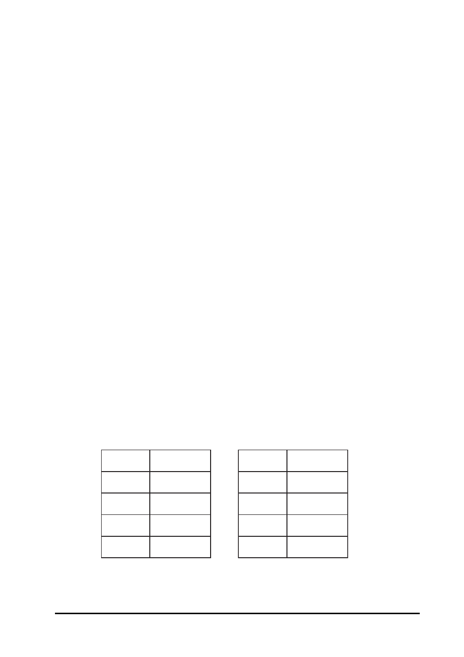
1.9 Configuration Tables
e
d
o
C
e
t
a
r
d
u
a
B
3
0
0
0
2
1
4
0
0
0
4
2
5
0
0
0
8
4
6
0
0
0
6
9
e
d
o
C
e
t
a
r
d
u
a
B
7
0
0
0
2
9
1
8
0
0
0
4
8
3
9
0
0
0
6
7
5
A
0
0
0
2
5
1
1