Kleenmaid KED2000 User Manual
Page 8
8
Ductwork
To ensure optimum performance, the
ducting system of the dryer should be
as short as possible with a minimum
number of elbows. Your dryer will work
best when the venting system has as
few air flow restrictions as possible.
Exhaust ducting which is longer than
recommended may extend drying time,
cause lint to accumulate and affect
dryer performance and dryer lifeĆtime.
Where possible, smooth, rigid ducts
should be used with a diameter of at
least 100 mm.
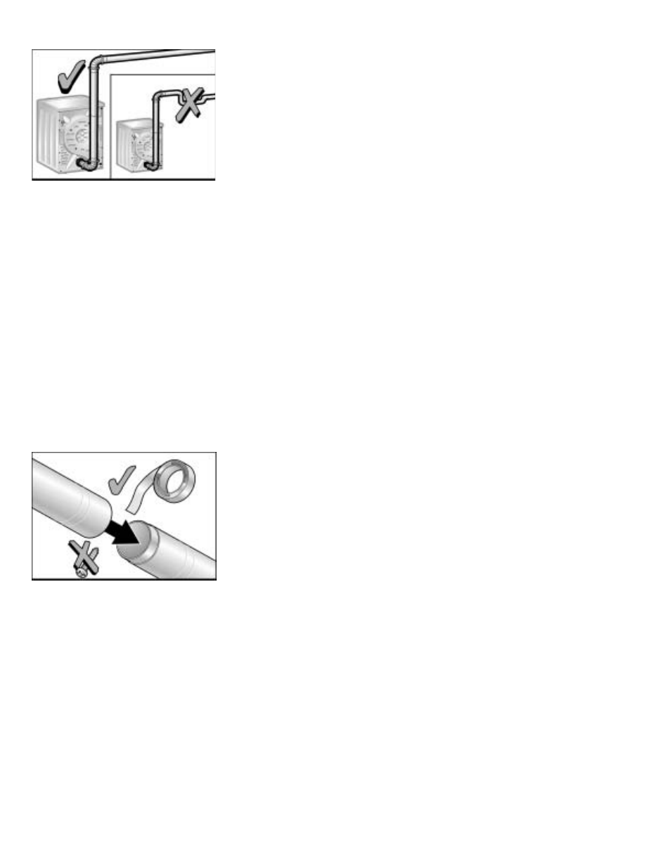
DO NOT assemble the ductwork with
screws or fasteners that extend into
the duct. They will serve as an
accumulation point for lint.
Joints should be secured with aluĆ
minum tape.
All joints should be tight to avoid leaks.
The male end of each duct section
must point away from the dryer.
Whether connecting to an existing
venting system or a new venting
system, make sure that all ducting
is clean and free of lint.
Pressure drops
The length and type of exhaust air duct
used can impede air flow, especially
angle elbows with a small radius. →
Diameter reductions and pressure
drops (resistances) should be kept to
a minimum.
d
The following should be avoided
-
Long exhaust air ducts.
-
Exhaust air ducts with a small
crosĆssection.
-
Exhaust air ducts with many bends
and angle joints
Pressure drops due to friction
Air flow is influenced by frictional
resistances in the duct and/or tube,
ie. by friction on the inside of the
exhaust air duct, and can be effected
in the following ways:
-
the smoother the internal wall
-
the larger the diameter of the
internal wall
-
the shorter the tube
The lower the frictional resistance.
Pressure drops due to fittings
Exhaust air is subject to additional
resistance from fittings, e.g. from
bypass adapters (elbows, bends, angle
joints), wall boxes fitted with a grill or
a oneway flap.
Installation with tube connection -
inside diameter - 100 mm
To ensure the minimum air flow
requirement, a specific pressure
drop (resistance) must not be
exceeded.
The total permissible pressure drop for
an exhaust air duct must not exceed a
specific numerical value. It is calculated
from the sum of all the individual presĆ
sure drop values taken both from the
straight sections and from the fittings
in the exhaust air duct.
Enlarge the inside diameter of the duct
connection when connecting a duct
connection with an inside diameter
of 100 mm and a total pressure drop
of 50*.
* To determine the total pressure drop
value see the table on Page 9.
d
The numerical value for the
maximum permissible total
pressure drop in an exhaust
air duct is 50 (see chart below).