Gpi port circuitry details – JLCooper eBOX User Manual
Page 51
51
Details
e
nced
pin 1 of the GPI Input Port.
he internal pullup resistor insures that the input pin is set to a
nown st
he d fault s ate of e GPI nputs +5 vo ts or
stat
1’
G
es
it
T
ter
ull
or a
o
m
‘dry con
o
cte
e
P
t
d
d
o
th
example below.
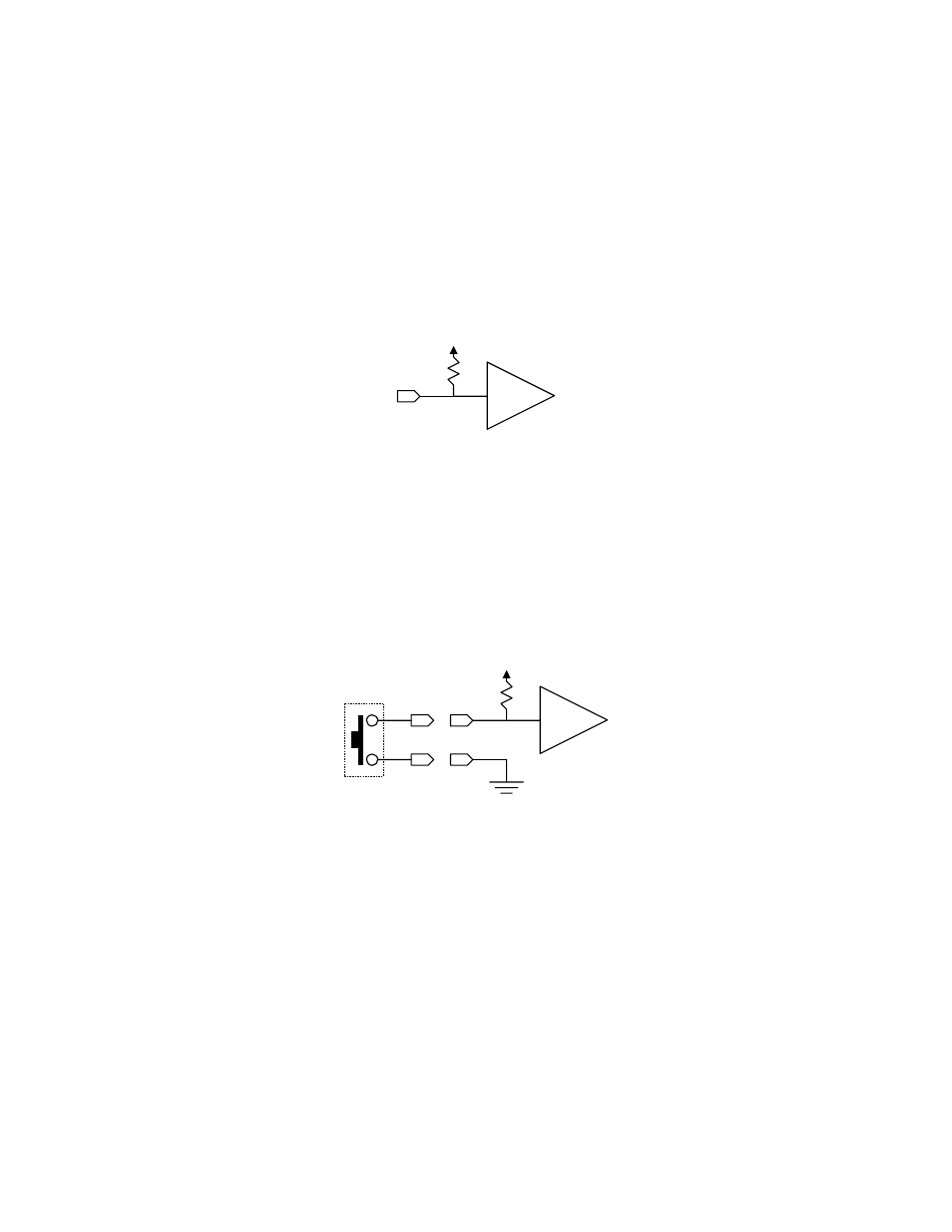
GPI Port Circuitry
The eBOX GPI input and output circuits are detailed in th
following section.
The inputs of the eBOX GPI ports are CMOS inputs. The input
circuitry has a 4700 ohm pullup resistor to +5 volts as refere
to
Note: Because the inputs are CMOS, the input voltage MUST be
limited to voltage levels between 0 and 5 volts. If this is not possible,
consider using the eBOX I/O.
5 Volts
4700Ω
74HC244
Detail of GPI Input
T
k
ate. T
e
t
th
I
is
l
a
logic
e of ‘ in the PI m sage b map.
he in nal p up
resist
lso all ws a si ple switch or
tact’ t be
conne
d betw en a G I Inpu pin an groun as sh wn in e
4700Ω
74HC244
5 Volts
GPI Input Example with Pushbutton Switch
1
2