3 installing the sensor – Guralp Systems CMG-5T Compact User Manual
Page 7
Operator's Guide
2.3
Installing the sensor
You will need a hard, clean surface such as a concrete floor, to install the
5T Compact.
If you are in any doubt about how to install the sensor, you should
contact Güralp Systems.
1. Prepare the surface by scribing a N/S orientation line and
installing a grouted-in fixing bolt on the line, near the middle. A
6mm (0.25 inch) threaded stud is suitable, as is an expanding-nut
rock bolt or anchor terminating in a threaded stud. The bolt
should be about 120mm (5 inches) long.
2. Place the accelerometer over the fixing bolt and rotate to bring the
orientation line and studs accurately into registration with the
scribed base-line.
3. Level the sensor, using its adjustable feet, until the bubble lies
entirely within the inner circle of the level indicator.
The feet are mounted on screw threads. To adjust the height of a
foot, turn the brass locking nut anticlockwise to loosen it and
rotate the entire foot so that it screws either in or out. When you
are happy with the height, tighten the brass locking nut clockwise
to secure the foot. The locking nut must be tightened so that it
moves to the bottom of its travel: although the foot will also be
locked if the nut is at the top of its travel, performance will be
reduced.
The instrument can use internal simulated level adjustment to
compensate for tilt, as long as it is fixed within 1 ° of the
horizontal.
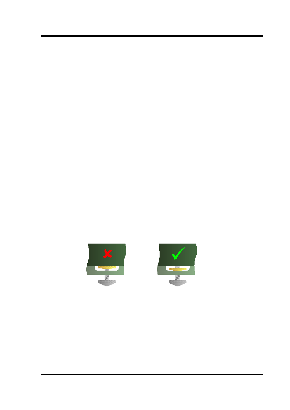
4. Secure the accelerometer in place using a fixing nut with spring
washer. Do not screw down the instrument too tightly, as the
casing may be deformed.
5. If required, make a screening box for the sensor to shield it from
draughts and sharp changes of temperature. A suitable box can be
constructed from expanded polystyrene slabs (e.g. 5 cm building
May 2011
7