Guralp Systems CMG-5T Compact User Manual
Page 18
CMG-5T Compact
signal received from the instrument by a recording system with a
differential input will be twice the true value. For example, the
calibration sheet may give the acceleration response as “2 x 0.50 V/ms
-2
”,
indicating that this factor of 2 was not included in the value given.
Caution: Never ground any of the differential outputs. If you are
connecting to a single-input recording system, you should use the
signal ground line as the return line and ignore the inverting output.
3.4.2
Frequency response
The poles and zeroes table describes the frequency response of the
sensor. If required, you can use the poles and zeroes to derive the true
ground motion mathematically from the signal received at the sensor.
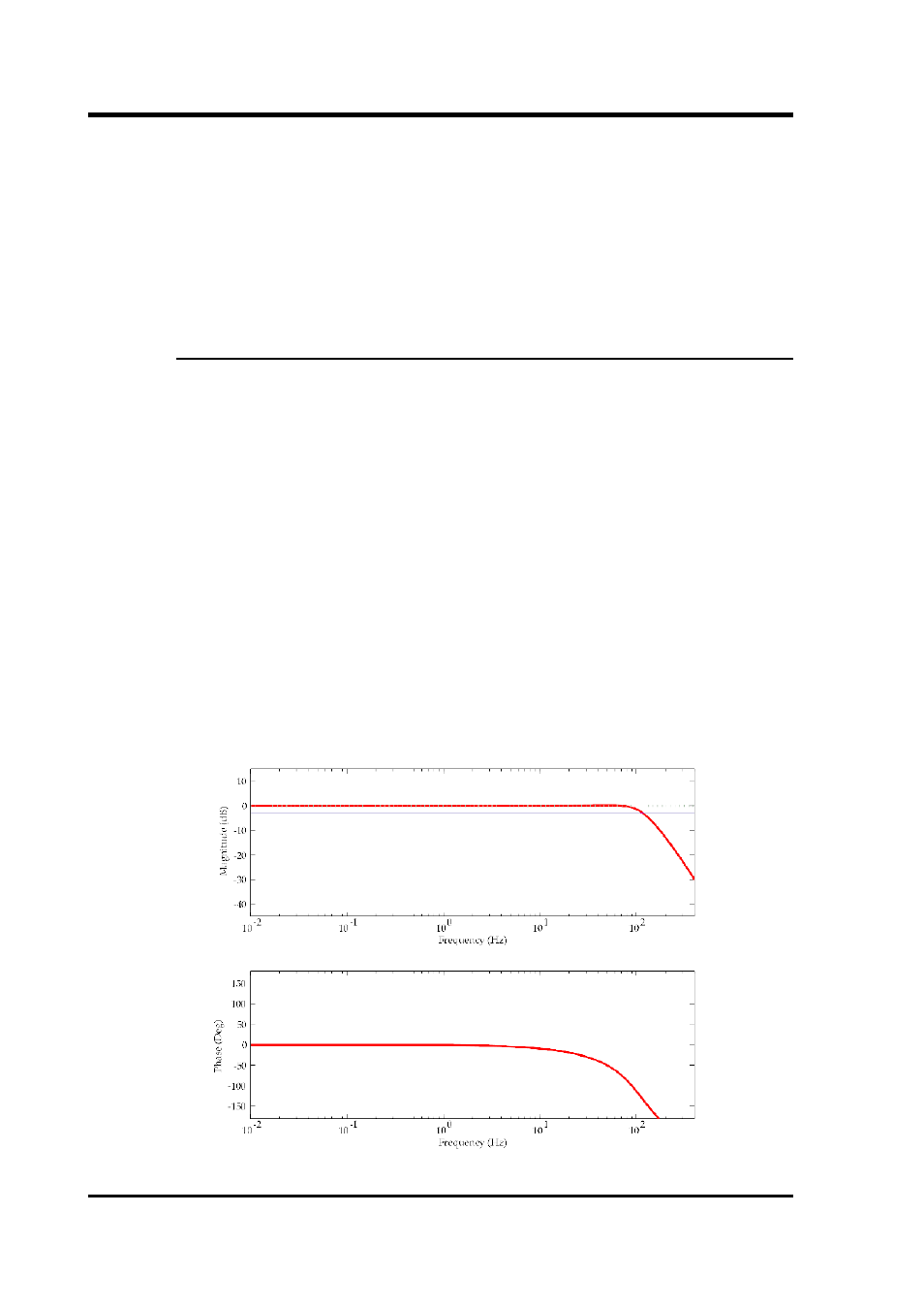
The 5T Compact is designed to provide a flat response (to within 3dB)
over its passband.
Güralp Systems performs frequency response tests on every sensor at the
time of manufacture. All records are archived for future reference. The
results of these tests are provided with the sensor.
When testing the instrument to confirm that it meets its design
specification, the range of frequencies used are concentrated over about
3 decades (i.e. 1000 : 1) of excitation frequencies. Consequently, the
frequency plots of each component are provided in normalised form.
Each plot marks the frequency cut-off value (often quoted as “-3dB” or
“half-power” point).
18
Issue E