2 electrical connections – Guralp Systems CMG-5T Compact User Manual
Page 22
CMG-5T Compact
The normalising constant A is calculated at a normalising
frequency value fm = 1 Hz, with s = j fm, where j = √–1.
•
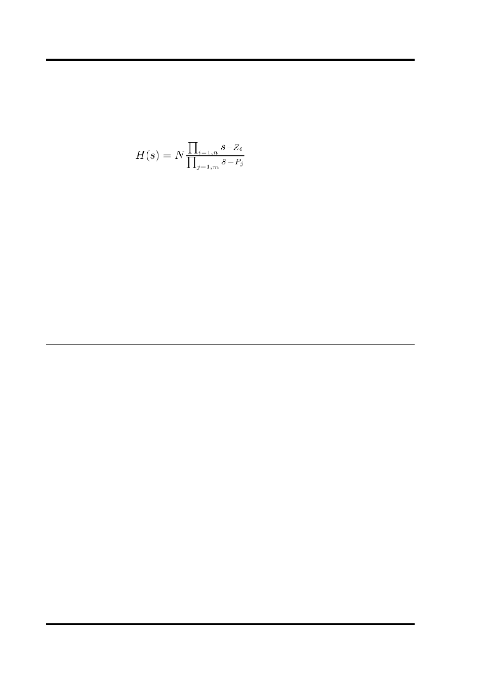
H(s) is the transfer function of the sensor, which can be expressed
in factored form:
In this equation z
n
are the roots of the numerator polynomial,
giving the zeroes of the transfer function and p
m
are the roots of
the denominator polynomial, giving the poles of the transfer
function.
In the calibration pack, G is the sensitivity given for each component on
the first page, whilst the roots z
n
and p
m
, together with the normalising
factor A, are given in the Poles and zeroes table. The poles and zeroes
given are measured directly at Güralp Systems' factory using a spectrum
analyser. Transfer functions for the vertical and horizontal sensors may
be provided separately.
4.2
Electrical connections
Each channel inside the 5T Compact sensor has four output lines: a pair
of differential outputs with low gain and another pair with high
(nominally 10 ×) gain.
Optionally, the second gain block can be configured at the factory to act
as a high-pass filter to remove the DC offset at the output terminal. This
filter can have a corner frequency of 0.05 Hz (20 s) or 0.025 Hz (40 s). In
these instruments, the gain at the additional outputs is set to × 1 (unity).
The output offsets of a high-pass filtered output cannot be zeroed using
the DC offset adjustment screws; in any case, this offset should not be
more than ± 1 mV. The high-pass filtered output is likely to take around
5 times the time constant of the high-pass circuit to settle down. This
time constant is detailed on the calibration sheet, together with
accurately-measured frequency values.
The two pairs of output lines are balanced about signal ground so that
either differential drive or single-ended drives of opposite polarity
(phase) are available. For a single-ended drive, the signal ground must
be used as the signal return path. You must not ground any of the active
output lines, as this would allow damaging currents to flow through the
output circuits. Also, if single-ended outputs are used, the positive
acceleration outputs must be the ones interfaced to the recorder.
22
Issue E