I/o setup menu – Greenheck Microprocessor Controller v3.0 (469690) User Manual
Page 12
12
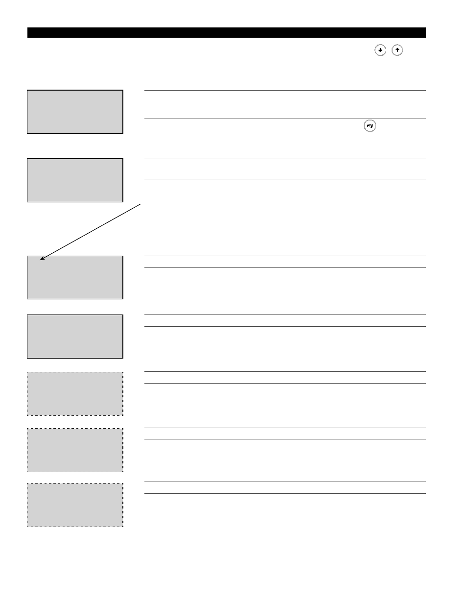
Access the I/O SETUP menu through the Main Menu. Scroll through the menu screens using the
keys.
Sensor Calibration: Measure the actual temperature and find the difference from the Sensor Temp
(uncalibrated). This difference becomes the Offset and once the Offset is input to the
controller, the Actual Temp should match the actual measured temperature.
***ACCESS DENIED***
Enter Password:0000
WRONG PASSWORD
T
HIS
SCREEN
CAN
BE
LOCKED
TO
PREVENT
TAMPERING
WITH
THE
SETTINGS
.
F
ROM
THE
FACTORY
,
ACCESS
IS
NOT
PASSWORD
PROTECTED
TO
ALLOW
QUICKER
START
-
UP
.
To set the password, go to the
‘PROGRAM’
menu by pressing the
button.
Once there, scroll down until you arrive at the Change Password screen. The ‘Level 2’
password protects the
‘I/O SETUP’
menu.
Setups for DDC
Analog & Digital
Inputs/Outputs
T
HE
‘I/O SETUP’
MENU
IS
USED
TO
SET
UP
THE
ANALOG
&
DIGITAL
INPUT
/
OUTPUTS
.
B1 Outside:NTC
Sensor Temp:
000.0ºF
Offset =
00.0ºF
Actual Temp:
000.0ºF
T
HIS
SCREEN
DISPLAYS
THE
OUTSIDE
AIR
TEMPERATURE
ENTERING
THE
UNIT
.
NOTE: The wiring terminal for each I/O is displayed in the respective screens.
B2 Supply:NTC
Sensor Temp:
000.0ºF
Offset =
00.0ºF
Actual Temp:
000.0ºF
T
HIS
SCREEN
DISPLAYS
THE
SUPPLY
DISCHARGE
TEMPERATURE
.
B3 Cold Coil:NTC
Sensor Temp:
000.0ºF
Offset =
00.0ºF
Actual Temp:
000.0ºF
T
HIS
SCREEN
DISPLAYS
THE
AFTER
COOLING
COIL
TEMPERATURE
.
This screen only appears if a cooling system was selected.
B4 Room Temp:NTC
Sensor Temp:
000.0ºF
Offset =
00.0ºF
Actual Temp:
000.0ºF
T
HIS
SCREEN
DISPLAYS
THE
ROOM
TEMPERATURE
.
This screen only appears if the room supply sensor is wired between B4 and BC4 on
the controller.
B4 Input
Max cooling demand.
Input Status:Open
T
HIS
SCREEN
DISPLAYS
THE
STATUS
OF
THE
DIGITAL
INPUT
TO
TERMINAL
B4.
This screen only appears if the room supply sensor is NOT wired between B4 and
BC4 on the controller.
When the Input Status is Open, the unit will operate normally and adjust the discharge
temperature based on outdoor air temperature. When the Input Status is Closed (in the
case of a digital input, ie. Thermostat), this indicates that a digital call for cool is being
received by the controller. The controller then overrides the outdoor air temperature
discharge control and sends the supply temperature set point to the supply reset
minimum temperature (Max cooling: 55
ºF,adj. in ‘SET POINTS’ menu).
I/O SETUP MENU
Sensor Temp is the sensor’s uncalibrated output.
Offset is for calibrating the sensor.
Actual Temp is the new calibrated sensor output.