Greenheck Microprocessor Controller v3.0 (469690) User Manual
Installation, operation and maintenance manual, Ddc controller for energy recovery, Read and save these instructions
®
PART #469690
DDC CONTROLLER
for ENERGY RECOVERY
Installation, Operation and Maintenance Manual
READ AND SAVE THESE INSTRUCTIONS
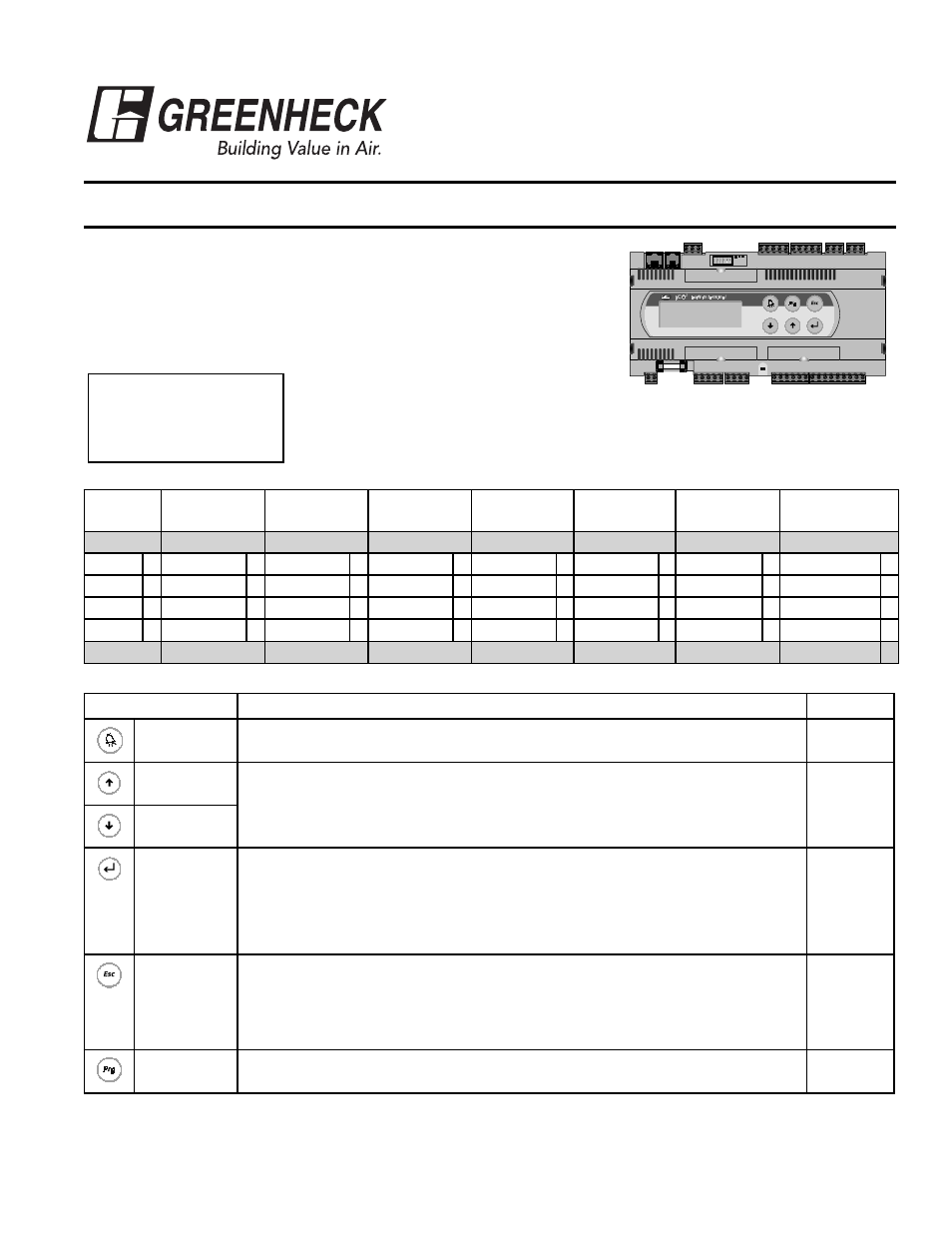
MANEUVERING THROUGH THE CONTROLLER
The DDC controller is located in the control panel on the energy recovery unit.
The face of the DDC controller has six buttons allowing the user to perform
various tasks such as viewing conditions or changing set points. A brief
description of the six buttons is provided. For additional details, refer to the
page references included.
Prior to accessing the controller, confirm the functions that were provided with
the unit by referencing the DDC Code shown
on the controller Start-Up screen.
The Start-Up screen appears when power is applied to the controller. The program version
and code are shown on this screen. The code shows the user what components and
functionality were provided with the unit and also dicates how the program operates. Below
is a description of the code.
Greenheck Fan Corp.
ER DDC v3.##
Code: GY2X000B
Name
Heat
Cool
HGRH
Frost
Economizer
UnOccupied
Mode
Communications
G
Y
2
X
0
0
0
B
GFC
G None – Disable
X None – Disable
X None – Disable
X None – Disable
0 None – Disable
0 None – Unit Off
0 None
X
Enable
Y CW
C On/Off
A Timed Off
1 On/Off
1 Cycle on Room
1 Modbus
M
PDx 1 stg
1
Mod
B Preheat
2 Modulating
2
LON
L
PDx 2 stg
2
Modulating
3
BACNet
B
GFC
Enable
PDx 2 stg
None – Disable
None – Disable
None – Disable
None – Unit Off
BACNet
Description
Reference
Alarm
Indicates both visually on the controller (the button lights up) and to the Building
Management Systems (BMS) (field-wired) that something is not functioning normally.
Page 3
Up Arrow
The arrow keys allow the user to scroll through different screens and adjust
parameters.
Page 3
Down Arrow
Enter
A. In screens with adjustable parameters, pressing the Enter key moves the cursor
from the upper left corner of the screen to the parameter. The arrow keys can
then be used to adjust the parameter.
B. To move to the next parameter on the same screen, press the Enter button.
C. To save the change, press the Enter button until the cursor moves back to the
upper left corner of the screen.
Page 3
Escape
Allows the user access to the Main Menu. The following adjustments can be made:
Page 4
• Unit Status
• Set Points
• Manual Overrides
• Analog & Digital Input/Output Setup
• Time Clock Setup
• Miscellaneous Information
• Unit On/Off
Program
Allows the user access to the Program Menu
Page 17
NOTE: If this controller needs to be interfaced with a BMS (ie: Lonworks, BACnet or Modbus), please refer to page 23 for an integration points list.