Lights out in fire (optional), Extra fire relay (optional), Extra exhaust relay (optional) – Greenheck Kitchen Fan Control Center (475730) User Manual
Page 9
9
Kitchen Fan Control Center
Lights Out In Fire (Optional)
This option will turn off the kitchen hood lights in
the event of a fire without the use of a shunt trip
breaker. If provided, this option will be factory wired.
Normal light circuit wiring should be followed. Please
see either Switches (Optional), Lights on page 7
or Combination Light/Fan Switch on page 8 for
additional wiring information.
NOTE
For lights out in fire option, light circuit must not
exceed 900W maximum.
NOTE
Relay contacts will be dry. Power will need to be
provided to the common terminal on each set.
Do not use additional relay contacts for power
interruption to appliances. Contacts are rated up to
250 VAC and 8 amps maximum.
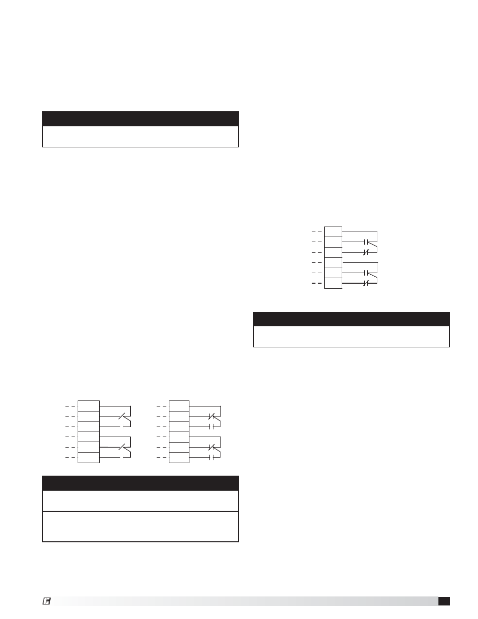
Extra Fire Relay (Optional)
The KFCC can include additional fire relays for shunt
trips, alarms, or additional utilities that need control
signals to be sent in the event of a kitchen fire. The
additional relay’s state will only be changed if the
dedicated fire system is wired into the KFCC. Wiring
from additional relays to terminals will be done in the
factory.
First Additional Fire Relay
• Power to terminal C9
• From terminal NO9 (normally open; closes in fire) to
device
• From terminal NC9 (normally closed; opens in fire)
to device
• Power to terminal C10
• From terminal NO10 (normally open; closes in fire)
to device
• From terminal NC10 (normally closed; opens in fire)
to device
Second Additional Fire Relay
• Similar to what is displayed above regarding
terminals C11, NO11, NC11 and C12, NO12 and
NC12.
NC10
NO10
A
B
B
BR
BK
NC9
C10
BK
RD
A
NO9
C9
BR
RD
R5
R5
12
14
11
22
21
24
R6
C12
NC11
NO12
NC12
B
A
B
BR
BK
BK
RD
R6
C11
NO11
A
RD
BR
12
14
11
22
21
24
EF Relay #2 contacts on R8 on terminal groups 15/16
RD
NO7
NC7
NO8
NC8
A
B
B
A
C8
C7
R4
BK
RD
BR
BR
BK
R4
12
14
11
22
21
24
NOTE
Relay contacts will be dry. Power will need to be
provided to the common terminal on each set.
Extra Exhaust Relay (Optional)
The KFCC can include additional relays for devices that
activate when the exhaust fan is running. Wiring from
additional relays to terminals will be done in the factory.
First Additional Exhaust Relay
• Power to terminal C7
• From terminal NO7 (normally open; closes with
exhaust) to device
• From terminal NC7 (normally closed; opens with
exhaust) to device
• Power to terminal C8
• From terminal NO8 (normally open; closes with
exhaust) to device
• From terminal NC8 (normally closed; opens with
exhaust) to device
Second Additional Exhaust Relay
• Similar to what is displayed above regarding
terminals C15, NO15, NC15 and C16, NO16, and
NC16.
®