Water wash control panel (wwcp) interface, Supply fan failure indicator (optional), Exhaust fan failure indicator (optional) – Greenheck Kitchen Fan Control Center (475730) User Manual
Page 10: Status lights (optional), Extra supply relay (optional)
10
Kitchen Fan Control Center
Water Wash Control Panel (WWCP) Interface
The KFCC may have to be interfaced with a Greenheck
Water Wash Control Panel (WWCP). In these cases, the
WWCP “Start Fan” and “Stop Fan, Start Wash” push
buttons should be used for manual fan operation.
WWCP
• From terminals 3 and 4 in the WWCP to terminal
S1H and S1 in KFCC
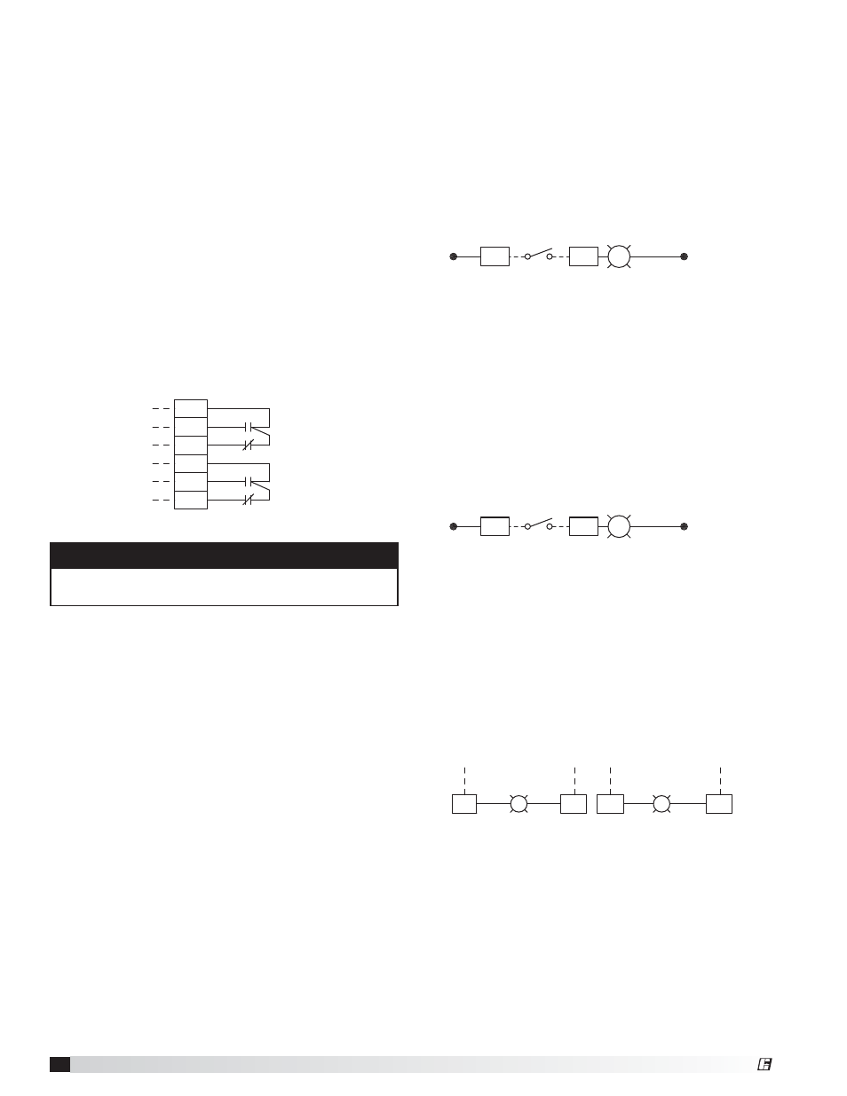
Supply Fan Failure Indicator (Optional)
This option will provide a small indicator light on the
front panel of the KFCC. A field provided air proving
switch located in the supply duct needs to be wired to
a set of terminals, which will illuminate this light and
provide a visual if the supply fan is not operating when
the fans are on.
Air Flow Switch (field provided)
• To terminals AF3 and AF4
LT3
PR
WH
AF3
AF4
G
AF2
SF Failure Light
SUPPLY AIR FLOW SWITCH FIELD WIRED
Exhaust Fan Failure Indicator (Optional)
This option will provide a small indicator light on the
front panel of the KFCC. A field provided air proving
switch located in the exhaust duct needs to be wired
to a set of terminals, which will illuminate this light and
provide a visual if the exhaust fan is not operating when
the fans are on.
Air Flow Switch (field provided)
• To terminals AF1 and AF2
LT2
PR
WH
AF1
AF2
G
AF1
EF Failure Light
EXHAUST AIR FLOW SWITCH FIELD WIRED
Status Lights (Optional)
The option adds status lights to the face of the KFCC.
They will be either 120 VAC or 24 VAC status lights and
will be noted on the wiring diagram. Power will have to
be provided for each light in the field.
Status light(s)
• Bring power to SL1 and a neutral to SL2
(1st status light)
• Bring power to SL3 and a neutral to SL4
(2nd status light)
LT
SL1
SL2
120V STATUS LIGHT
LT
SL3
SL4
120V STATUS LIGHT
Example of two 120 VAC Status Lights
Extra Supply Relay (Optional)
The KFCC can include additional relays for devices that
activate when the supply fan is running. Wiring from
added relays to terminals will be done in the factory.
First Additional Supply Relay
• Power to terminal C5
• From terminal NO5 (normally open; closes in fire) to
device
• From terminal NC5 (normally closed; opens in fire)
to device
• Power to terminal C6
• From terminal NO6 (normally open; closes in fire) to
device
• From terminal NC6 (normally closed; opens in fire)
to device
Second Additional Supply Relay
• Similar to what is displayed above regarding
terminals C13, NO13, NC13 and C14, NO14, and
NO6
RD
B
NC6
BK
B
A
A
NC5
C6
NO6
RD
BR
C5
NO5
BK
BR
R3
R3
y
12
14
11
22
21
24
SF Relay #2 contacts on R7 on terminal groups 13/14
NOTE
Relay contacts will be dry. Power will need to be
provided to the common terminal on each set.
®