Thermostat - hood mounting – Greenheck Kitchen Fan Control Center (475730) User Manual
Page 4
4
Kitchen Fan Control Center
1. Locate the exhaust duct on top of the hood. A 3/4
to 7/8-inch
(19.0 to 22.2 mm)
diameter hole must
be cut into the duct 2 inches
(50.8 mm)
above the
hood top. Center the hole along the side of the duct.
Make sure that the resistive temperature detector will
not interfere with any fire system nozzles, or other
items installed in the exhaust duct. If an exhaust fire
damper is present the hood exhaust collar, it must be
removed prior to temperature sensor installation.
2. Place the J-box plate inside of the octagon extension
ring and place over the hole in the exhaust collar.
3. Disassemble the compression seal and place through
hole in duct collar and J-box plate as shown. Tighten
the nut inside the octagon extension ring.
4. Place the resistive temperature detector through the
compression seal and tighten the compression fitting.
5. Refer to Electrical Connections section for
instructions on wiring the temperature sensor.
6. Install the cover for the octagon box.
2 inches
(50.8 mm)
Hood Exhaust Collar
Front Side
0.75 to 0.875 inch
(19.0 to 22.2 mm)
diameter hole
Octagon Extension
PN 830125
Lock Washer
Nut
1/4-inch Compression Seal
PN 463570
J-Box Plate
PN 732396
Gasket
Temperature Sensor (RTD)
PN 384925
Octagon Cover
PN 380926
Resistive Temperature Detector(s)
- Duct Collar Mounting
NOTE
The resistive temperature detector(s), or RTD(s), will
be provided only if the digital temperature interlock
option was configured/ordered with the unit. If it
wasn’t, continue to the next section.
Resistive temperature detector(s) may be factory
installed. If so, continue to the next section.
NOTE
The thermostat will be provided only if the thermostat
style temperature interlock option was configured/ordered
with the unit. If it wasn’t, continue to the next section.
The thermostat may be factory installed. If so,
continue to the next section.
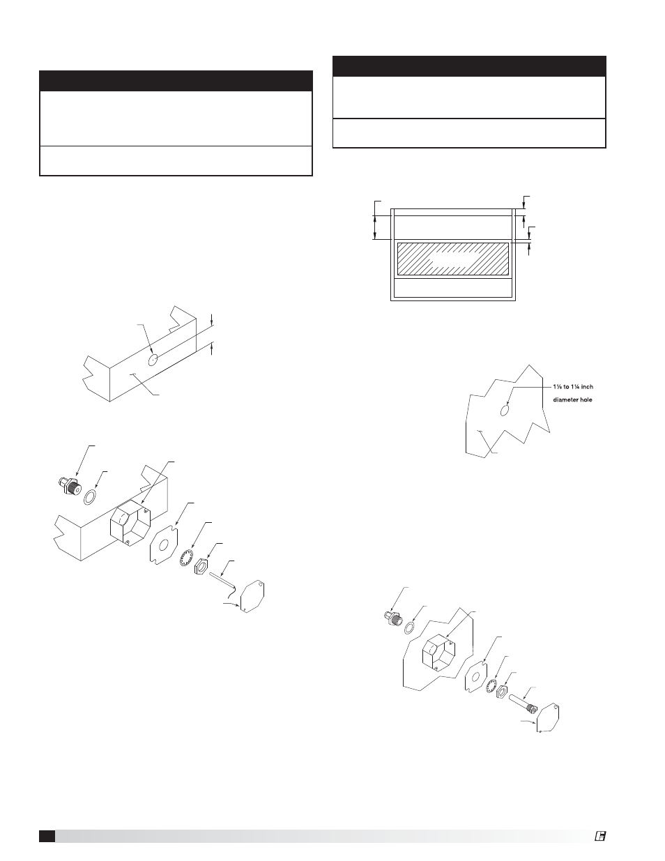
Thermostat - Hood Mounting
Hood Plan View
19.525 inches
3 inch air space
2 inch typical
Exhaust Area
Supply Area
(optional)
Sensor Install
(cut out area)
1. Locate the flat area(s) at the top interior of the hood in
front of the filters, towards the front of the hood. A 1
1
⁄
8
to 1¼ inch (
28.58 to 31.75 mm)
diameter hole must
be cut into the top of
the capture tank. Make
sure the thermostat
will not interfere with
the fire system nozzles
and is not within eight
inches
(20.32 cm)
of
the light fixtures.
2. Place the J-box plate inside of the octagon extension
ring and place over the hole.
3. Insert the Evergreen compression seal fitting into the
hole from the inside the hood, making sure the gasket
is placed on the fitting before inserting it into the
hole. Install the J-box plate, lock washer, and 1-1/2
inch (38 mm) nut over the threaded portion of the
compression seal fitting and tighten securely.
Recommended thermostat mounting location is in the
flat interior of the hood and at least 8 inches
(20.32 cm)
from light fixture.
Hood Surface
(28.58 to 31.75 mm)
4. Place the thermostat detector through the
compression seal and tighten the compression fitting
to 35 ft-lbs.
5. Refer to Electrical Connections section for
instructions on wiring the thermostat.
6. Install the cover for the octagon box.
Gasket
5/8-inch Compression Seal
PN 452614
Nut
Lock Washer
Octagon Extension
PN 830125
J-Box Plate
PN 732396
Octagon Cover
PN 380926
Thermostat
PN 383923
®