Temperature interlock – digital (optional), Temperature interlock – thermostat (optional) – Greenheck Kitchen Fan Control Center (475730) User Manual
Page 11
11
Kitchen Fan Control Center
NOTE
Do not connect temperature sensors in series.
Separate as much as possible the probe and digital
input cables from inductive loads and power cables,
to avoid any electromagnetic disturbances. Never
lay power and probe cables in the same cable
conduits (including those for the electrical panel).
Loosen every screw and insert the cable end. Next,
tighten the screws and gently pull the cables to
check their tightness.
Temperature Interlock – Digital (Optional)
When configured with digital temperature interlock, the
KFCC will include RTD sensors and digital controllers.
Wiring from terminal blocks to controllers will be done
in the factory. Use two 18 AWG stranded thermostat
wires from each temperature sensor to the appropriate
terminal blocks in the KFCC. (See the table below for
connection options). In temperature sensor junction
box, connect leads on RTD to the 18 AWG conductors
using appropriate size wire nuts. These conductors for
each sensor are not polarity sensitive.
RTD Sensors
Choose the final connection option based on the table.
T1-A
T1-B
TS1
TC1
6
8
7
1
2
T2-A
T2-B
TS2
Wiring example of first two
Digital Temperature Interlock Sensors
Sensor
Terminals
First Sensor
T1-A and T1-B
Others
(if applicable)
T2-A and T2-B
T3-A and T3-B
T4-A and T4-B
T5-A and T5-B
T6-A and T6-B
T7-A and T7-B
T8-A and T8-B
T9-A and T9-B
T10-A and T10-B
T11-A and T11-B
T12-A and T12-B
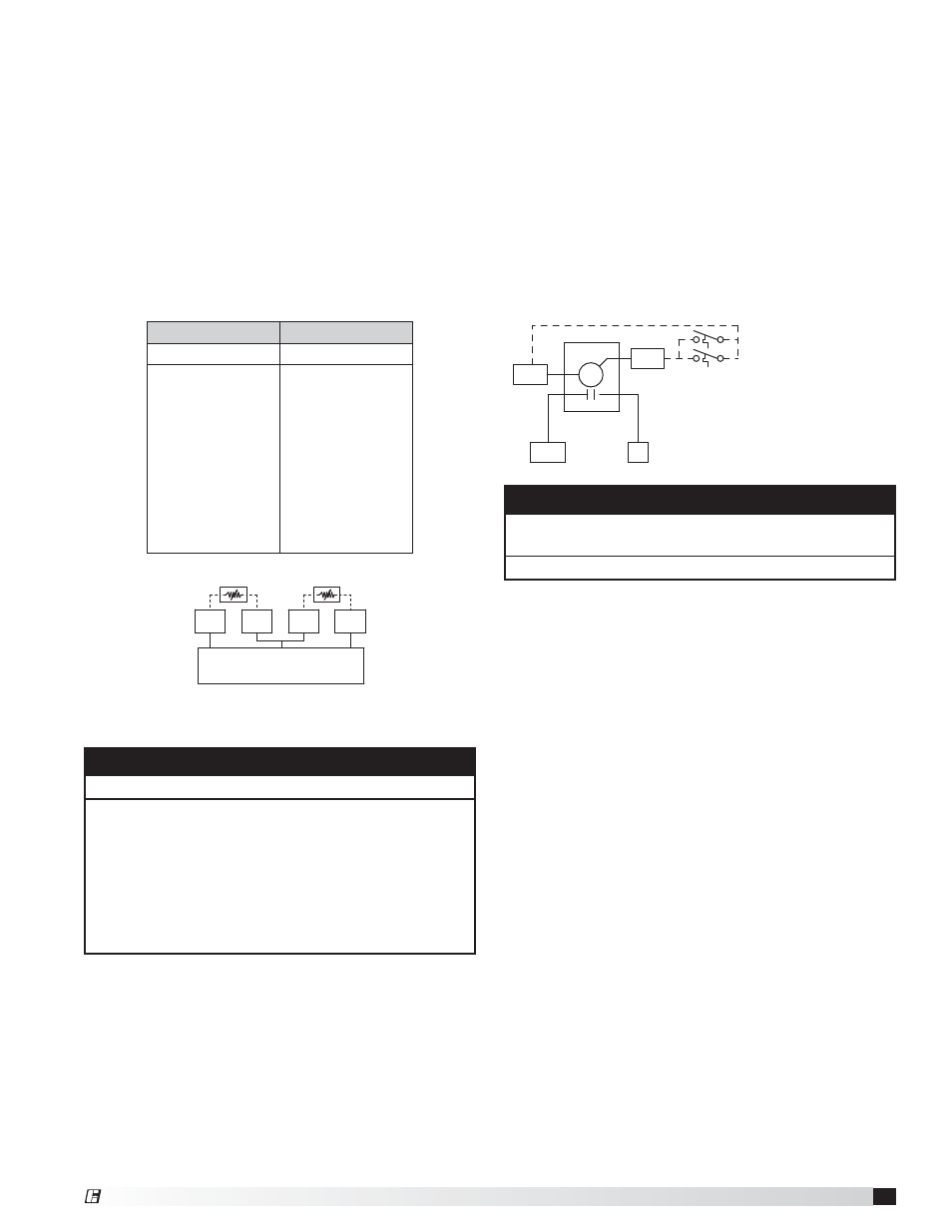
Temperature Interlock – Thermostat (Optional)
When configured with thermostat style, temperature
interlock, the KFCC will include thermostat(s) and a
time delay relay. Wiring from terminal blocks to the
time delay relay will be done in the factory. Use two 14
AWG 90°C minimum conductors from each thermostat
to the appropriate terminal blocks in the KFCC. In
the thermostat junction box, connect leads on the
thermostat to the 14 AWG conductors using appropriate
size wire nuts. These conductors for each thermostat
are not polarity sensitive.
Thermostat(s)
• To terminals T1-A and T1-B
NOTE
Wire thermostats in parallel if multiple thermostats are
utilized.
Do not connect thermostats in series with each other.
S1
S1H
S1
S1H
TS1
6
1
2
R9
NO
C
T1-A
T1-B
TS2
TYP. 1 SENSOR PER
EXHAUST COLLAR
WIRED IN PARALLEL
(Off Delay: 1-100 minutes)
®