Fire system integration, Spare fire relay, Switches (optional) – Greenheck Kitchen Fan Control Center (475730) User Manual
Page 7
7
Kitchen Fan Control Center
NOTE
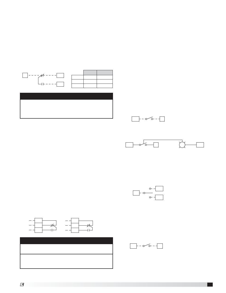
C2, NC2, and NO2 terminals are provided for a
second fire system microswitch. These terminals
are not wired to any components; they are simply
provided for a connection point only.
C
NO
BK(YW)
RD(RD)
C1
NC
FS1
BR(BK)
NO1
NC1
Fire System Integration
A dedicated fire system microswitch needs to be wired
into the KFCC. During a fire, this will disengage supply
starters, and therefore turn off corresponding supply
fans. If KFCC is configured with “Exhaust in Fire”
option, the KFCC will also engage the exhaust starters,
therefore turning on exhaust fans in the event of a fire.
Dedicated Fire System Microswitch
• Common to terminal C1
• Normally-closed to terminal NC1
• Normally-open to terminal NO1
NOTE
Relay contacts will be dry unless otherwise noted on
the panel’s specific wiring diagram.
Do not use additional relay contacts for power
interruption to appliances. Contacts are rated up to
250 VAC and 8 amps maximum.
Spare Fire Relay
The KFCC includes additional fire relay contacts
standard for shunt trips, alarms, or additional utilities
that need control signals to be sent in the event of a
kitchen fire. The additional relay’s state will only be
changed if the dedicated fire system is wired into the
KFCC. Wiring from added relays to terminals will be
done in the factory.
Fire Relay
• Power to terminal C3
• From terminal NO3 (normally open; closes in fire) to
device
• From terminal NC3 (normally closed; opens in fire)
to device
• Power to terminal C4
• From terminal NO4 (normally open; closes in fire) to
device
• From terminal NC4 (normally closed; opens in fire)
to device
12
14
B
A
NC3 BK
C3
NO3
RD
BR
NO4
NC4
A
B
R2
11
C4
22
BK
21
24
RD
BR
R2
Fan, 1-Speed
• To terminals S1H and S1* (first fan switch)
• To terminals S2H and S2* (second fan switch)
• To terminals S3H and S3* (third fan switch)
*S1N, S2N and S3N used if lighted toggle switches are
utilized.
Ship Loose
Fan Switch Example
S1
S1
S1H
S1
S1H
Control Cabinet Mounted, Fan Switch Example
(Factory Wired)
S1
R
LT1
S1N
S1
S1H
S1
Switches (Optional)
A switch panel may be supplied to operate lights, fans,
heating/cooling capabilities of a tempered supply, a
damper, or another component of the kitchen exhaust
system. If selected, the switch(es) will be provided one
of four ways:
1. Shipped loose for remote mounting
2. Mounted on the hood
3. Mounted on the hood utility cabinet
4. Mounted on a wall utility cabinet
If the switches and the KFCC are both mounted on the
same hood, wiring to the fan switches will be done in
the factory.
Lights
• To terminals H2 and B2 (first light switch)
• To terminals H3 and B3 (second light switch)
• To terminals H4 and B4 (third light switch)
S-1
B2
H2
Fan, 2-Speed
• To terminals S1F, S1, and S1S
(first 2-speed fan switch)
S1
LO
S1
HI
S1S
S1F
Ship Loose, 2-Speed
Fan Switch Example
ANSUL
®
AMEREX
®
COM
RD
(RD)
N.C.
BR
(BK)
N.O.
BK
(YW)
®