Audible alarm (optional), Power for shunt trip (optional), Make-up air (mua) interface (optional) – Greenheck Kitchen Fan Control Center (475730) User Manual
Page 8
8
Kitchen Fan Control Center
Audible Alarm (Optional)
With this option, an alarm will be provided and mounted
on the panel that will sound in the event of a kitchen
fire. This option will be factory-mounted and wired if
selected.
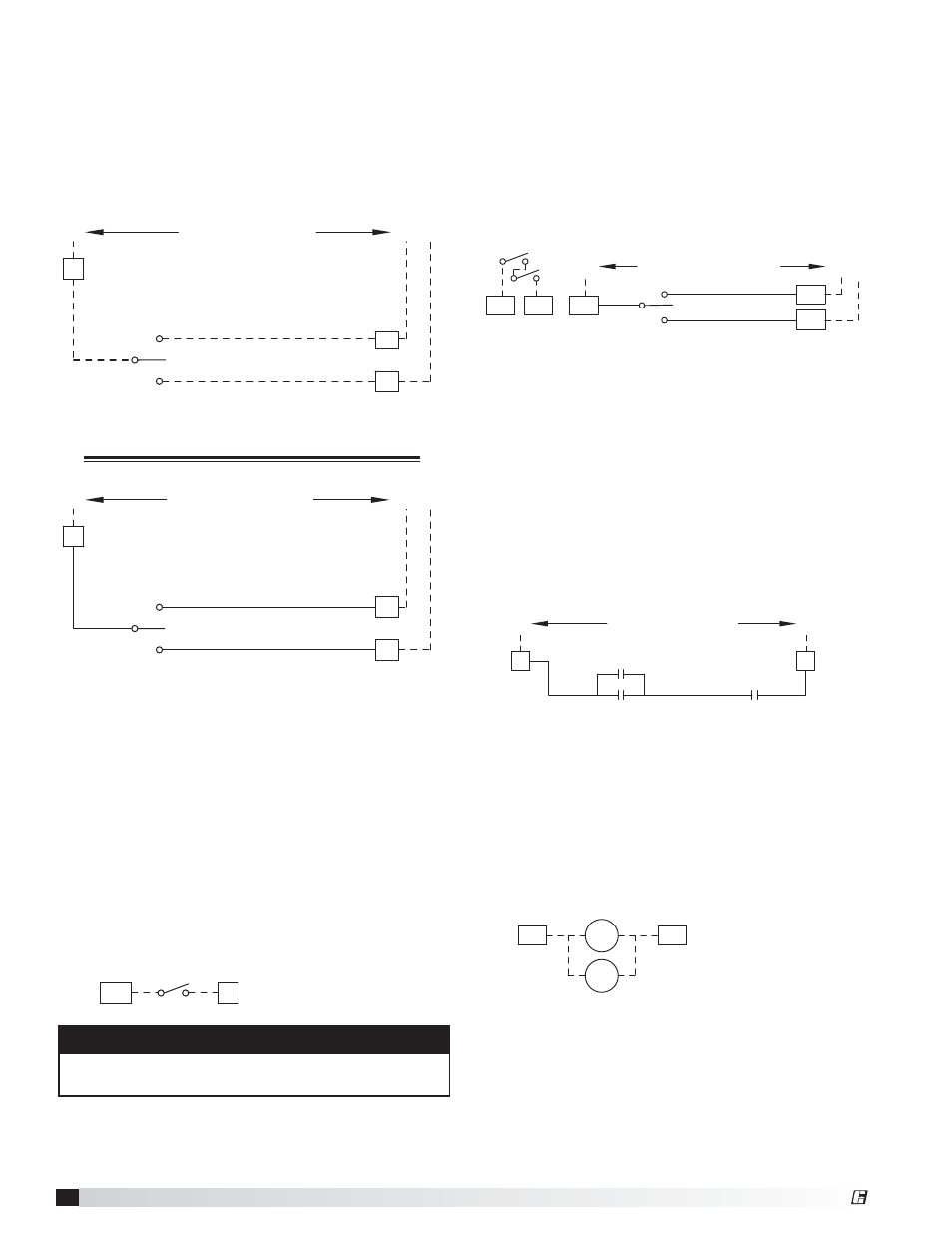
Auto-Damper Switch on KFCC (mounted in hood)
• From limit switch to terminals AD1 and AD2
• From terminal 3 in auto-damper controller to AD3 in
KFCC
• From terminal 4 in auto-damper controller to AD4 in
KFCC
• From terminal 5 in auto-damper controller to AD5 in
KFCC
CONNECTIONS TO
DAMPER CONTROLLER
4
S6
BL
TEST
RESET
AD4
BL
AD3
BL
AD5
5 3
AD1
AD2
To Damper
Limit Switches
Power for Shunt Trip (Optional)
If the KFCC is configured with the power for shunt
trip option, the KFCC will have terminals to connect
an externally provided shunt trip breaker coil to
allow the breakers to be tripped in the event of a fire.
Connections include:
(Externally provided) shunt trip breakers
• To terminals STH and STN
STH
STB1
STB2
STN
Make-Up Air (MUA) Interface (Optional)
When the KFCC is interfaced with another Greenheck
supply air unit, this option will omit the redundant
starter in the KFCC, as the supply air unit will already be
provided with one. This will be 24 VAC voltage; so 18
AWG, shielded control wire can be utilized.
Make-Up Air Unit
• From terminal R in MUA control center to terminal R
in KFCC
• From terminal G in MUA control center to terminal G
in KFCC
R
R
13 14
R12
BL
G
G
BL
CONNECTIONS TO
TEMPERED MUA FAN
11 14
13 14
TYP. THRU ALL
EXHAUST STARTERS
Tempered Supply, Heat Only
• To terminals R and W1
Tempered Supply, Cool Only
• To terminals R and Y1
Tempered Supply, Heat and Cool
• To terminals R (common), W1 (heat), and Y1 (cool)
Connections from these terminals will have to be made
to the respective supply fan terminals R, W1 (if used),
and Y1 (if used). Use proper gauge wire for field wiring
depending on the voltage used.
When connecting to manufacturer’s tempered unit,
connect R, W1 (if used), and Y1 (if used) up to the
supply unit and land on R, W1 (if used), and Y1 (if
used). This will be 24 VAC power, so 18 AWG wire
should be utilized.
R
R
CONNECTIONS TO
TEMPERED MUA FAN
Switch Mounting - Ship Loose for Remote Mounting
OFF
S3-1
COOL
Y1
Y1
HEAT
W1
W1
Shipped Loose
Make-Up Air Tempering Switch Example
R
R
CONNECTIONS TO
TEMPERED MUA FAN
Switch Mounting - On Control Package
BL
OFF
S3-1
COOL
BL
Y1
Y1
HEAT
W1
BL
W1
Mounted on Control Package
Make-Up Air Tempering Switch Example
Combination Fan/Light Switch
• To terminals S1H and S1
S1
S1
S1H
NOTE
For combination light/fans option, light circuit must
not exceed 900W maximum.
®