Installation, Control box mounting, Switch mounting – Greenheck Kitchen Fan Control Center (475730) User Manual
Page 3: Resistive temperature detector(s) - hood mounting
3
Kitchen Fan Control Center
Installation
NOTE
All field installation of electrical equipment must be
done to meet all NEC and electrical codes.
Control Box Mounting
Locate an area with enough space to mount the control
box and securely fasten to the wall. Use appropriate
type fasteners depending on the mounting location.
Avoid installing the control box in environments with
high magnetic and/or radio frequency interference.
NOTE
Control box may be factory mounted. If so, continue
to the next section.
Switch Mounting
Locate an area with enough space to mount the
switches junction box and fasten to the wall.
NOTE
If the switches were NOT shipped loose, provided in a
separate junction box, continue to the next section.
Resistive Temperature Detector(s)
- Hood Mounting
NOTE
The resistive temperature detector(s), or RTD(s), will
be provided only if the digital temperature interlock
option was configured/ordered with the unit. If it
wasn’t, continue to the next section.
Resistive temperature detector(s) may be factory
installed. If so, continue to the next section.
2. Cut a 3/4 to 7/8-inch
(19.0 to 22.2 mm)
diameter hole
in the flat spot of the capture
tank. Make sure the
resistive temperature
detector(s) will not
interfere with fire
system nozzles and is
not within 12 inches of
light fixtures.
0.75 to 0.875 inch
(19.0 to 22.2 mm)
diameter hole
Hood Surface
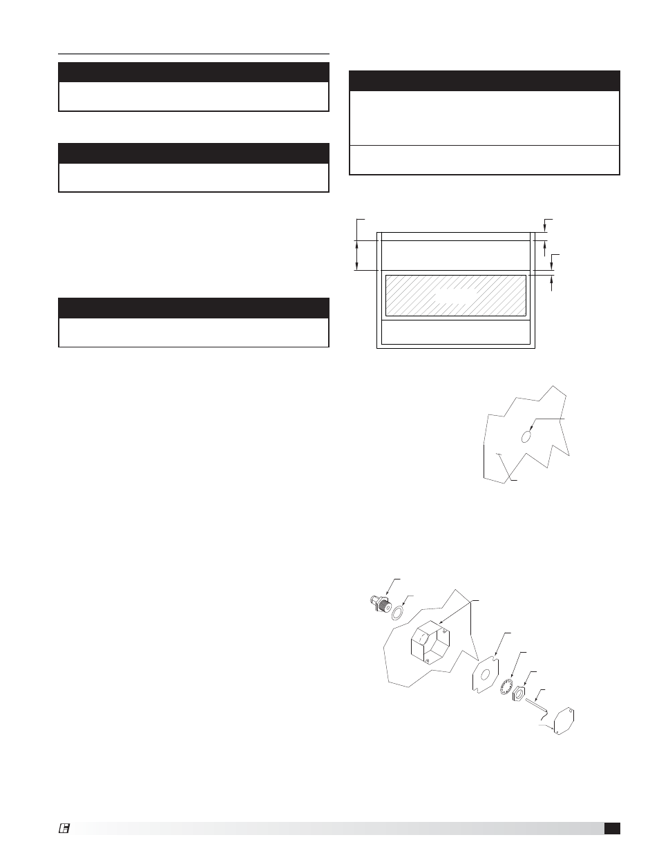
1. Locate flat area(s) at the top interior of the hood in
front of the filters, towards the front of the hood.
3 inch air space
2 inch typical
19.525 inches
Sensor Install
(cutout area)
Exhaust Area
Supply Area
(optional)
P.O.BOX 410 SCHOFIELD,
TITLE
INSTR, ADJ.
Top View of Exhaust Hood
3. Place the J-box plate inside of the octagon extension
ring and place over the hole.
4. Disassemble the compression seal and place through
hole and J-box plate as shown. Tighten the nut inside
the octagon extension ring.
5. Place the resistive temperature detector through the
compression seal and tighten the compression fitting.
6. Refer to Electrical Connections section for
instructions on wiring the temperature sensor.
7. Install the cover for the octagon box.
Octagon Extension
PN 830125
Lock Washer
Nut
1/4-inch Compression Seal
PN 463570
Gasket
J-Box Plate
PN 732396
Temperature Sensor (RTD)
PN 384925
Octagon Cover
PN 380926
-BOX PLATE INSIDE OF THE
TENSION RING, AND PLACE OVER HOLE.
E THE COMPRESSION SEAL AND PLACE
®