Electrical connections, Power for starters and fans, Power for kfcc – Greenheck Kitchen Fan Control Center (475730) User Manual
Page 6: Power for hood lights (optional)
6
Kitchen Fan Control Center
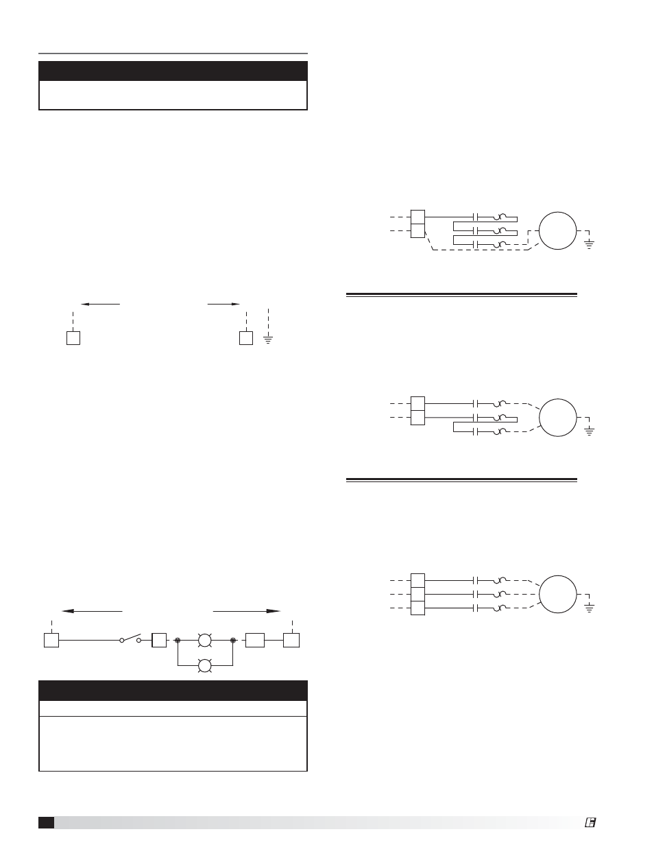
Power for Starters and Fans
The KFCC is equipped with contactors that may have
thermal overloads attached to them. Each fan should
have a designated power source. The breaker size
(amps), wire gauge, phase, and voltage for each fan is
specified on the KFCC wiring diagram. Two speed fans
will require two separate starters.
200/208/230/277 VAC Single Phase Fan(s) Power
Wiring
• LINE - from breaker to terminals L1 and L2
• LOAD, 200/208/230/277 VAC - from T1 and T3 on
the bottom of contactor/overload to fan disconnect
Single phase, 200/208/230/277 VAC
Wiring Connection Example
208/1 phase
2 wire
from breaker
L2
INPUT POWER
L1
OL2
ST2
T1
L1 T1
T2
L2 T2
T3
L3 T3
G
Exh
FAN 2
115 VAC Single Phase Fan(s) Power Wiring
• LINE - from breaker to terminals L1 and L2
• LOAD, 115 VAC - from terminal block L1 and T3 on
the bottom of contactor/overload to fan disconnect
115/1 phase
2 wire
from breaker
L2
INPUT POWER
L1
N
OL1
ST1
T1
L1 T1
T2
L2 T2
T3
L3 T3
G
Exh
FAN 1
Single phase, 115 VAC
Wiring Connection Example
Three Phase Fan(s) Power Wiring
• LINE - from breaker to terminals L1, L2 and L3
• LOAD - from T1, T2 and T3 on the bottom of
contactor/overload to fan disconnect
Three phase, Wiring Connection Example
200V, 208V, 230V, 460V, and 575V also available
208/3 phase
3 wire
from breaker
L3
L2
INPUT POWER
L1
OL3
ST3
T1
L1 T1
T2
L2 T2
T3
L3 T3
G
Exh
FAN 3
NOTE
Light circuit must not exceed 1400W maximum.
Hood lights may be directly wired to light switch,
creating unoccupied terminals B2, B3 and B4. Please
refer to the wiring diagram specifically created for the
panel on the inside door of the control center.
Electrical Connections
NOTE
All field wiring of electrical equipment must be done to
meet all NEC and electrical codes.
The extent of field wiring required will depend on the
options and general configuration of the KFCC. Each
option is broken out in the next portion of this manual.
Each option will either be factory wired or will require
field wiring. Use 14 AWG, 60°C copper wire unless
otherwise specified.
Power for KFCC
The KFCC needs a power source to operate all inner
components. This power source cannot be on a shunt
trip breaker; the power must remain constant to the
panel, even in the event of a kitchen fire.
Power for KFCC
• 120 VAC, 15 amp circuit to terminals H1 and N1
CONTROL INPUT:
120 VAC, 15 AMPS FROM BREAKER
H1
L1
N1
N
G
Power for Hood Lights (Optional)
If the KFCC is configured for hood light control, a
separate power source for each light circuit will need
to be run to the panel as well to power the lights. The
KFCC can provide up to three light circuits.
Power for Hood Lights
• 120 VAC, 15 amp circuit to terminals H2 and N2
(first light circuit)
• 120 VAC, 15 amp circuit to terminals H3 and N3
(second light circuit)
• 120 VAC, 15 amp circuit to terminals H4 and N4
(third light circuit)
Hood Lights
• To terminals B2 and W2 (first light circuit)
• To terminals B3 and W3 (second light circuit)
• To terminals B4 and W4 (third light circuit)
LIGHT INPUT: 120 VAC,
15 AMPS FROM BREAKER
1400W max.
H2
S-1
L1
LT
LT
N2
N
BK
B2
W2
WH
®