System jumper table – GAI-Tronics ICP9000 Navigator Series Console Installation and Service Manual User Manual
Page 29
ICP9000 Navigator Installation and Service Manual
Installation
25
12/10
System Jumper Table
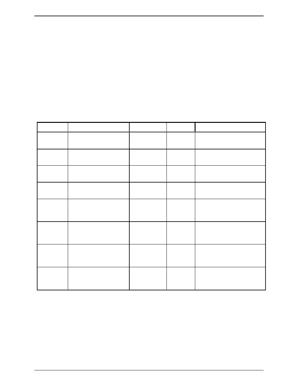
Table 12 is provided to assist the installer in determining the correct placement of console slave board
jumpers, for various system configurations. Each ICP9000 Navigator MCU is equipped with one CSD
slave board for ICPN9004A (4 channels), two slave boards for ICPN9008A (8 channels) and three slave
boards for ICPN9012A (12 channels) operation.
Each channel can be individually configured to support 2-wire, 4-wire, bridging, or terminating modes of
operation (parallel or single console). Refer to Figure 9.
The ICP9000 Navigator MCU is shipped with all line termination resistors in place. For parallel
operation of multiple consoles, the last console on any particular line should have its 2W or 4W
termination jumpers in place and any intermediate console should have the line termination jumpers
removed.
Table 12. CSD Slave Unit Table
Channel Function Jumper
No.
Position
Condition
Ch. 1, 5, 9
4W RX Termination
JU603
IN
OUT
600 ohm (default)
Parked – Bridging Impedance
Ch. 2, 6, 10 4W RX Termination
JU607
IN
OUT
600 ohm (default)
Parked – Bridging Impedance
Ch. 3, 7, 11 4W RX Termination
JU611
IN
OUT
600 ohm (default)
Parked – Bridging Impedance
Ch. 4, 8, 12 4W RX Termination
JU615
IN
OUT
600 ohm (default)
Parked – Bridging Impedance
Ch. 1, 5, 9
TX Source Impedance
2W RX Termination
Impedance
JU601 IN
OUT
600 ohm (default)
Parked – Bridging Impedance
(parallel console)
Ch. 2, 6, 10 TX Source Impedance
2W RX Termination
Impedance
JU605 IN
OUT
600 ohm (default)
Parked – Bridging Impedance
(parallel console)
Ch. 3, 7, 11 TX Source Impedance
2W RX Termination
Impedance
JU609 IN
OUT
600 ohm (default)
Parked – Bridging Impedance
(parallel console)
Ch. 4, 8, 12 TX Source Impedance
2W RX Termination
Impedance
JU613 IN
OUT
600 ohm (default)
Parked – Bridging Impedance
(parallel console)