Chapter 2 installation instructions – Foxconn X38A User Manual
Page 22
16
Chapter 2 Installation Instructions
5
1
4
8
Connect a 4-pin power
plug here
FDD Connector: FLOPPY
This motherboard includes a standard Floppy connector, supporting [360KB,
5
1
/4 in], [1.2MB, 5
1
/4in], [720KB, 3
1
/2 in], [1.44MB, 3
1
/2 in], [2.88 MB, 3
1
/2 in] FDDs.
IDE Connectors: PIDE
This connector supports the provided Ultra DMA 133/100/66 IDE hard disk ribbon
cable and you can configure as a disk array through RAID controller.
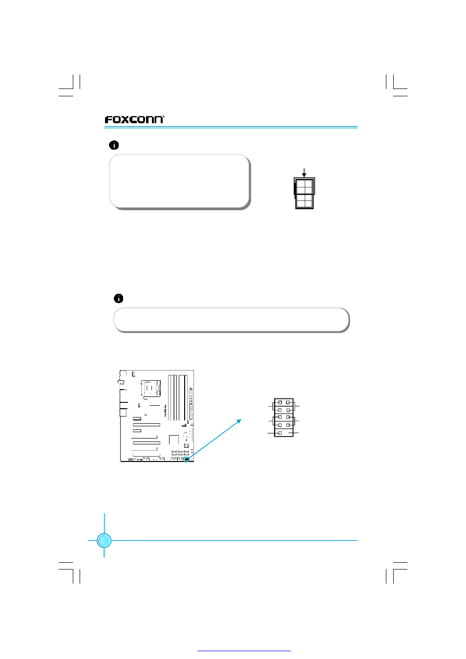
Front Panel Connector: FP1
This motherboard includes one connector for connecting the front panel switch
and LED indicators.
Hard Disk LED Connector (HD_LED)
The connector connects to the case’s IDE indicator LED indicating the activity
status of hard disks.
Reset Switch (RESET)
Attach the connector to the Reset switch on the front panel of the case; the
system will restart when the switch is pressed.
Attention:
We recommend you use 8-pin ATX 12V
power supply. If you want to use 4-pin
power supply, you need to align the ATX
power connector according to the right
picture.
NC
HD_LED
RESET
PWR_LED
PWRSW
9
10
1
2
FP
FP1
!
+
-
+
-
Empty
Front Panel Connector
Attention:
If you install two IDE devices, you must configure the second drive
as a slave device.
PDF 文件使用 "pdfFactory" 试用版本创建