DFI G7B630-B User Manual
Page 41
41
2
Hardware Installation
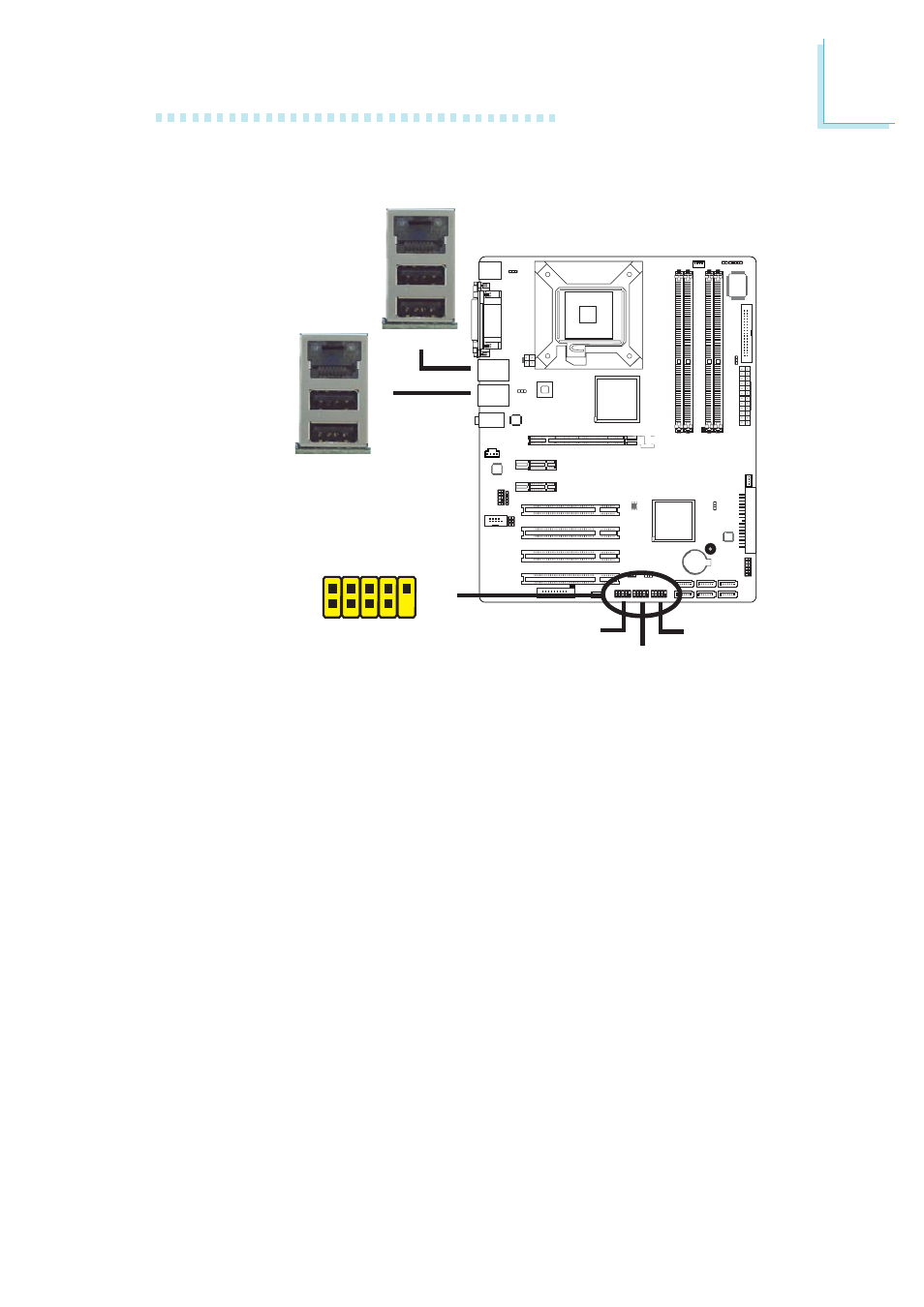
Universal Serial Bus Connectors
The system board supports 10 USB 2.0/1.1 ports. USB allows data
exchange between your computer and a wide range of simultane-
ously accessible external Plug and Play peripherals.
Four onboard USB 2.0/1.1 ports (Black) are at locations CN5 (USB
2-3) and CN6 (USB 0-1) of the system board.
The J9 (USB 4-5), J10 (USB 6-7) and J11 (USB 8-9) connectors
allow you to connect 6 additional USB 2.0/1.1 ports. The additional
USB ports may be mounted on a card-edge bracket. Install the
card-edge bracket to an available slot at the rear of the system
chassis then insert the connector that is attached to the USB port
cables to J9, J10 and/or J11.
BIOS Setting
Configure the onboard USB in the Integrated Peripherals submenu
(“USB Device Setting” section) of the BIOS. Refer to chapter 3 for
more information.
USB 4-5
W
W
W
USB 1
USB 0
USB 3
USB 2
USB 6-7
USB 8-9
1
VCC
-Data
+Data
GND
Key
VCC
-Data
+Data
GND
N.
C
.
2
1 0
9