Appendix c: rs/422 system (old signal converter) – Daktronics G-1000-34-R User Manual
Page 47
Appendix C
C-1
Appendix C: RS/422 System (Old Signal
Converter)
Daktronics is continually making improvements to our display systems in order to offer the highest quality
and latest technology in our products. This appendix covers the connections between the first display
and the Venus 1500 computer using the older signal converter.
Reference Drawings: System Riser Diagram (RS/422) . . . . . . . . . . . . . . . . . . Drawing A-88425
Signal/Power Termination Panel . . . . . . . . . . . . . . . . . Drawing A-88427
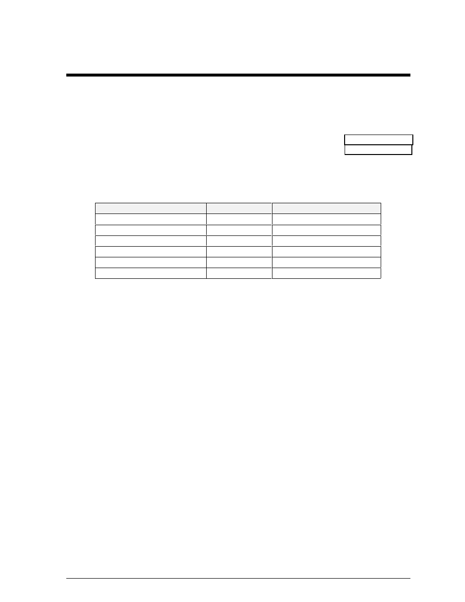
One end of the signal cable should be terminated to the 10 position terminal block labeled “DATA IN.”
Drawing A-88425 is an example of the termination panels. The other end is terminated at the signal
converter cable (Daktronics part number 0A-1137-0106) in the control room.
Pin No.
Field Cabling
Terminal Block (Data In)
Pin 1 (white) (Data TX-P)
White
Pin 4 (Data RX-P)
Pin 2 (blue) (Data TX-N)
Blue
Pin 5 (Data RX-N)
Pin 3 (green) (GND)
Green
Pin 6 (GND)
Pin 4 (black) (Data RX-P)
Black
Pin 2 (Data TX-P)
Pin 5 (brown) (Data RX-N)
Brown
Pin 3 (Data TX-N)
Pin 6 (red) (GND)
Red
Pin 1 (GND)
- TI-3031 4-Inch LED Bar-Digit Locker Room Clock (22 pages)
- ST-2005 Backlit & Non-Backlit Scorer’s Tables (24 pages)
- BB-2135 Backboard LED Light Strip (36 pages)
- TN-2563 Tuff Sport Indoor Multi-Court Tennis LED Scoreboard (112 pages)
- BB-2144 Tuff Sport Basketball LED Scoreboard (184 pages)
- TN-2607 Single-Court Outdoor LED Tennis Scoreboard (134 pages)
- CR-2004 Multi-Section Cricket Scoreboard (90 pages)
- FT-7150 Touchpad (29 pages)
- SW-2008 Aquatics/Track LED Scoreboard (84 pages)
- SO-1424-11 Multi-Section Outdoor LED Scoreboard (158 pages)
- FB-4005-31 DistaView Outdoor LED Scoreboard (64 pages)
- MS-2018 Generation III Stackable LED Scoreboard (76 pages)
- GM-2103 LED Gymnastics Scoreboards (38 pages)
- HS-200 Horn Start (36 pages)
- Indoor Hockey Goal Lights (44 pages)
- LED End-of-Period Basketball Lighting (34 pages)
- MS-2013 Portable LED Scoreboard (52 pages)
- WR-2106 Matside Jr. LED Wrestling Scoreboard (44 pages)
- TI-2021 Multipurpose Track & Field LED Timing Display (50 pages)
- P1647 Multi-Section Outdoor LED Scoreboard (50 pages)
- P1647 Multi-Section Outdoor LED Scoreboard (52 pages)
- DA-1200 Outdoor Decorative Accent (30 pages)
- 2000 Rodeo OmniSport (72 pages)
- Outdoor LED Scoreboards Installation (58 pages)
- Outdoor LED Scoreboards Service Manual (52 pages)
- SO-2014 Generation IV Multi-Section Outdoor LED Scoreboard (208 pages)
- P1647 Multi-Section Outdoor LED Scoreboard (44 pages)
- PC-2001 Pace Clock System (40 pages)
- PC-2002 Pace Clock System (32 pages)
- BB-314 Portable LED Basketball Scoreboard (28 pages)
- Protective Screen (4 pages)
- TI-2002 Portable LED Timer (32 pages)
- Radar Gun Speed of Pitch Interface (27 pages)
- TI-2026 Segment Timer (28 pages)
- Single-Section Outdoor LED Scoreboards (46 pages)
- LED Aquatics/Track Displays SW-2000 Series 10 Numeric Digit (86 pages)
- TI-2022 Portable LED Timer (32 pages)
- Single Section DistaView Outdoor LED Scoreboards Generation IV (99 pages)
- BB-2151 (NBA only) Transparent Shot Clock (48 pages)
- TN-2563 Tuff Sport Indoor LED Tennis Scoreboard (34 pages)
- Scoreboard Trumpet Horn (50 pages)
- ST-3001 Tuff Sport & ColorSmart LED Scorer’s Table (48 pages)
- Tuff Sport & ColorSmart Indoor LED Scoreboards (46 pages)
- Tuff Sport Indoor LED Scoreboards (40 pages)
- Tuff Sport& ColorSmart FourSided Indoor LED Scoreboards (58 pages)